
Login

Shoutbox
You must login to post a message.
renatoa
04/14/2024 5:56 AM
TheOtherJim and papajim,
 !
!
!allenb
04/11/2024 6:33 PM
Zemona

renatoa
04/11/2024 9:19 AM
Mrbones and sgupta,  ?
?
?renatoa
04/10/2024 1:09 AM
 , Ed K
allenb
04/09/2024 5:34 PM
TheJak99
Forum Threads
Newest Threads
War on Farmers by Su...Kaleido Roaster PID ...
Green coffee sellers
Wet beans - Estimati...
Skywalker roaster mods
Hottest Threads
| Skywalker roaster... | [292] |
| Skywalker, the AL... | [214] |
| Skywalker Roasts | [94] |
| My first popcorn ... | [47] |
| War on Farmers by... | [39] |
In Memory Of Ginny

Donations
Latest Donations
dmccallum - 10.00
JackH - 25.00
snwcmpr - 10.00
Anonymous - 2.00
Anonymous - 5.00
dmccallum - 10.00
JackH - 25.00
snwcmpr - 10.00
Anonymous - 2.00
Anonymous - 5.00
Users Online
Guests Online: 5
Members Online: 0
Total Members: 8,205
Newest Member: TheOtherJim
Members Online: 0
Total Members: 8,205
Newest Member: TheOtherJim
View Thread
Who is here? 1 guest(s)
 is this circuit right for fan control?
|
|
| jsutton |
Posted on 12/30/2010 6:01 PM
|
|
Newbie  Posts: 32 Joined: December 20, 2010 |
Is this circuit right for fan control? It has the dimmer in a different location than has been discussed in PopperyII threads here. http://mdmint.home.comcast.net/~mdmint/coffee/fancontrolproto.htm http://mdmint.hom...lproto.htm Here's the circuit schematic:  I see someone over at Coffee Geeks expressed a similar concern on this design: http://coffeegeek.com/forums/coffee/homeroast/356310 "I am in my second year of studying electrical engineering and some of the stuff people discuss still confuses me. I had a question on the frakenformer which I would like to ask and hopefully rather then hijack your thread it would add to it. PJK Said: A good illustration of this transformer / dimmer setup by the "frankenformer" guy himself is here: http://mdmint.home.comcast.net/coffee/fancontrolproto.htm I checked out that circuit and would love if someone could help explain it to me. I have never seen a transformer wired like that. It looks like it is wired to somehow give it self feedback. Why is it wired like this instead of how you would normally wire a transformer. I googled and checked my textbooks but have not been able to find any info on this method of wiring a transformer." I'd appreciate comments as I'm beginning my MODS having sourced all the parts today. Jim Edited by jsutton on 12/30/2010 6:18 PM |
|
|
|
| seedlings |
Posted on 12/31/2010 11:29 AM
|
 1 1/2 Pounder  Posts: 4226 Joined: June 27, 2007 |
I think you need the secondary reversed as it will have reverse polarity. Also, I don't know the benefit of having the dimmer on the higher voltage side of the transformer. I'd prefer to have it before the transformer, but it probably doesn't electrically matter much.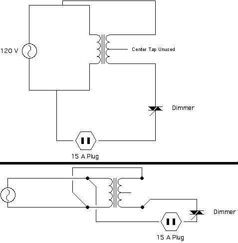 CHAD Roaster: CoffeeAir II 2# DIY air roaster
Grinder: Vintage Grindmaster 500 Brewers: Vintage Cory DCU DCL, Aeropress, Press, Osaka Titanium pourover |
|
|
|
| bvwelch |
Posted on 12/31/2010 11:34 AM
|
 1 1/2 Pounder Posts: 1064 Joined: December 27, 2007 |
Danger, Will Robinson -- that circuit is to boost an AC fan even higher than 120 volts by adding the secondary to the primary. The headline says "0 to 145 volts" |
|
|
|
| randytsuch |
Posted on 12/31/2010 1:05 PM
|
 1/2 Pounder  Posts: 394 Joined: June 20, 2009 |
I thought I remember someone trying to boost the voltage on a P2 fan, and not having success. They either burned it out, or didn't gain speed, I don't remember which, or where I read this. Also, the P2 has a DC fan, the circuit you so does not rectify, so I don't think it will work. P2's have a diode bridge before the fan. There is a P2 schematic at the bottom of this page http://members.sh...optwo.html I know a P1 or the original 1400 watt popcorn pumper, which has a 115V fan, will work fine with a voltage boost to the fan. EDIT maybe it will work. This guy did it. http://www.engadg...e-roaster/ Randy Edited by randytsuch on 12/31/2010 1:09 PM |
|
|
|
| seedlings |
Posted on 01/01/2011 9:19 AM
|
|
1 1/2 Pounder Posts: 4226 Joined: June 27, 2007 |
Oh, SHOOT! Is this a PII or a Cafe Rosto?... Randy (and Bill) are right, you'll blow a DC motor up giving her AC voltage. Are you going to boost voltage to the whole roaster entirely? CHAD Edited by seedlings on 01/01/2011 9:21 AM Roaster: CoffeeAir II 2# DIY air roaster
Grinder: Vintage Grindmaster 500 Brewers: Vintage Cory DCU DCL, Aeropress, Press, Osaka Titanium pourover |
|
|
|
| allenb |
Posted on 01/01/2011 12:39 PM
|
 Administrator Posts: 3858 Joined: February 23, 2010 |
The circuit Jim is showing is for a Cafe Rosto which, if it's like the Rosto I had a couple of years ago, it does have a 120 volt "universal" AC motor. The circuit is unlike anything I've ever come across having incoming 120 across both primary and secondary. It definitely won't work with a P2 with DC 20 volt motor. Instant vaporization when the dimmer is cranked! It's unfortunate that there are so many variations of circuits for AC and DC fan poppers that folks can easily get stuff crossed up if not extremely careful to triple check their design. Allen 1/2 lb and 1 lb drum, Siemens Sirocco fluidbed, presspot, chemex, cajun biggin brewer from the backwoods of Louisiana
|
|
|
|
| seedlings |
Posted on 01/01/2011 6:56 PM
|
|
1 1/2 Pounder Posts: 4226 Joined: June 27, 2007 |
Basically, the secondary is in series with the primary adding 25VAC, and it should work as long as the current limit on the secondary isn't reached. CHAD Roaster: CoffeeAir II 2# DIY air roaster
Grinder: Vintage Grindmaster 500 Brewers: Vintage Cory DCU DCL, Aeropress, Press, Osaka Titanium pourover |
|
|
|
| bvwelch |
Posted on 01/01/2011 10:30 PM
|
|
1 1/2 Pounder Posts: 1064 Joined: December 27, 2007 |
Trying to boost the heat with such a setup would not work -- the tranny is only rated for 2 amps and the popper will draw maybe 12 amps? |
|
|
|

| Jump to Forum: |
Similar Threads
| Thread | Forum | Replies | Last Post |
|---|---|---|---|
| Another Propane Gas Control Method | Electric and Gas Heat Sources | 31 | 10/14/2023 6:48 PM |
| Renatoa can you walk us through a roast based on Heat power control vs PID? | Roasting Coffee | 32 | 08/21/2023 12:41 AM |
| Unable to get Artisan Scope's PID to control heating | Dataloggers/Controllers/Rate of Rise Meters | 4 | 08/01/2023 9:11 AM |
| Problem with electric control Quest M6 Coffee Roaster | Quest M3 Roaster | 27 | 06/20/2023 3:39 AM |
| Gas control for bullet de aillio | R1 Bullet Roaster | 10 | 03/10/2023 11:13 PM |
Powered by PHP-Fusion Copyright © 2024 PHP-Fusion Inc
Released as free software without warranties under GNU Affero GPL v3
Designed with ♥ by NetriXHosted by skpacman