
Login

Shoutbox
You must login to post a message.
renatoa
07/26/2024 3:49 PM
Bill grubbe and Jk, 
allenb
07/26/2024 5:15 AM
Spiderkw Welcome to HRO!

renatoa
07/24/2024 8:31 AM
ramiroflores and John123,

 ?
?
?renatoa
07/21/2024 1:18 AM
 , Luislobo
renatoa
07/19/2024 11:28 AM
Koepea,
Forum Threads
Newest Threads
Skywalker roaster modsBackground Roast Iss...
Hello from Arkansas
TC4ESP
Green coffee reviews
Hottest Threads
| Skywalker roaster... | [375] |
| TC4ESP | [115] |
| War on Farmers by... | [47] |
| Adventures in flu... | [26] |
| Hello! (soon) Roa... | [17] |
In Memory Of Ginny

Donations
Latest Donations
dmccallum - 10.00
JackH - 25.00
snwcmpr - 10.00
Anonymous - 2.00
Anonymous - 5.00
dmccallum - 10.00
JackH - 25.00
snwcmpr - 10.00
Anonymous - 2.00
Anonymous - 5.00
Users Online
Guests Online: 8
Members Online: 0
Total Members: 8,394
Newest Member: Bill grubbe
Members Online: 0
Total Members: 8,394
Newest Member: Bill grubbe
View Thread
Who is here? 1 guest(s)
 TC4 - Overview and announcements
|
|
| JimG |
Posted on 05/10/2011 7:37 AM
|
|
1 1/2 Pounder  Posts: 834 Joined: October 23, 2008 |
The TC4 project is the brainchild of HRO member Bill Welch (bvwelch). His idea was/is to make available an open source, multiple channel data logging system designed specially for coffee roasters. There is a very long thread here that describes the evolution of the project. At the time of this posting, the TC4 has been brought along to the point of having a stable hardware configuration, along with several software applications. There is a googlecode repository that contains source code for the project software, as well as schematics and Eagle files for the board(s). There is also a link there where you can order a bare PCB to use for building your own TC4. In a nutshell, the TC4 consists of a 4-channel analog-to-digital converter (ADC), an on-board ambient temperature sensor, a small amount of circuitry to facilitate driving off-board devices (like solid state relays for electric heaters), and a variety of pin headers for connecting external components (like LCD displays). At present, the following applications are available for the TC4, with more in development: - Bourbon : roast monitor application with optional PC interface - Kona : PID roast control application with optional PC interface - aArtisan : turns the TC4 into a device usable with the Artisan Roasting Scope application - Catuai : roast monitor, with manual roaster control (in alpha stage) One of the unique features of the TC4 software library is that good routines have been developed to calculate the rate of rise of temperature (RoR) during coffee roasts, in real time. The ability to monitor RoR during roasts is embraced by many successful roasters. While the TC4 was developed with roasting in mind, people have used it for several other purposes, including BBQ/smoker control and espresso machine control. There is a series of threads on HRO dedicated to various aspects of the TC4. So before posting in this thread, please check and see if there is a different thread that is more appropriate. Jim
JimG attached the following image:

|
|
|
|
| JimG |
Posted on 05/10/2011 7:43 AM
|
|
1 1/2 Pounder Posts: 834 Joined: October 23, 2008 |
ANNOUNCEMENT The new shipment of TC4 PCB's (version 4.00) has arrived. The new boards, from DorkbotPDX, are very nice quality (and also very purple!). Bare boards can be purchased, at cost, here: http://www.mlgp-l...o-pcb.html There are also options to purchase boards with the SMD chips pre-soldered, or to purchase pre-built boards. I can usually keep up OK with the SMD boards since I had a stencil made. But if there is a significant demand for the pre-built boards, I will be looking for some volunteers! Jim
JimG attached the following image:

Edited by JimG on 05/10/2011 7:49 AM |
|
|
|
| JimG |
Posted on 05/19/2011 5:38 PM
|
|
1 1/2 Pounder Posts: 834 Joined: October 23, 2008 |
In response to a lot of requests, you can now order a complete DIY kit for the TC4. This kit contains everything needed to build the shield, except for a soldering iron and solder. All of the surface mount components will already be reflow soldered to the PCB. The through-hole components (2 resistors, 2 transistors, 2 capacitors, 1 reset switch, 4 wiring terminals, and a bunch of pin headers) are shipped loose and will need to be soldered to the board by the user. http://www.mlgp-l...o-pcb.html Jim |
|
|
|
| JimG |
Posted on 06/15/2011 9:24 PM
|
|
1 1/2 Pounder Posts: 834 Joined: October 23, 2008 |
I have added support for type T and type J thermocouples in the TC4 code repository. The new library, thermocouple.h, has not been fully tested, but all the preliminary checks I've done look good. I was running into problems with the thermocouple conversion coefficients taking up a lot of RAM. To the point where applications would crash if more than 2 thermocouple types were compiled into a sketch. So the new thermcouple library puts all of the coefficient tables into flash memory on the ATmega. This should make it possible for people to write applications where a different type of thermocouple can be connected to each of three TC4 input terminals. This library is easily extensible to other thermocouple types. So if there is a need to support materials besides type K, type T, and type J, please let me know. The new library, in pre-release status, is available here: http://tc4-shield...ermocouple Jim |
|
|
|
| JimG |
Posted on 07/30/2011 3:02 PM
|
|
1 1/2 Pounder Posts: 834 Joined: October 23, 2008 |
Unfortunately, I've come to the conclusion I just don't have time right now to offer fully built TC4's. It's great that so many people have ordered them, but all the soldering is killing me So, as of today, the option to buy a fully built TC4 has been taken off of the ordering page. But don't worry if you have already ordered a built board: all existing orders will be filled. Bare boards, boards with SMD's, and complete kits (DIY soldering required only for the through-hole components) will still be offered. If there is someone who would like to take over soldering duties and offer a fully built board, I am quite happy to supply you with whatever you need. Jim Edited by JimG on 07/30/2011 3:05 PM |
|
|
|
| JimG |
Posted on 09/19/2011 2:14 PM
|
|
1 1/2 Pounder Posts: 834 Joined: October 23, 2008 |
ANNOUNCING VERSION 5.20 OF THE TC4 Here are the improvements/changes incorporated in the new design: 1. All electronic components are now surface mounted. No more through-hole resistors, capacitors, transistors, etc. 2. A green power-indicator LED has been added to confirm that the shield is getting 5VDC. 3. PWM output pulses on OT1 and OT2 will blink individual red LED's to visually confirm output activity. 4. The I2C header has been moved to the edge of the board for easier access. 5. The parallel LCD connection header has been eliminated. LCD support using I2C adapters is strongly recommended instead. 6. Power for OT1 and OT2 is now provided, by default, from the Arduino's 5V voltage regulator. Previously, VIN was the source of power for OT1 and OT2. A solder jumper, and an empty spot for an optional Schottky diode, are provided on the TC4 for users wishing to use VIN instead. 7. A new port has been added (I/O2). In addition to providing another port for digital I/O, this port was added to facilitate AC power monitoring. Soon (I hope) there will be TC4 support for improved AC heater and motor control using "period skipping" and phase angle control. The new boards are compatible with all existing software written for the TC4, including support for Artisan. Switching all the electronics to SMD should make it much simpler for folks with only modest soldering skills to be able to build boards from the kits. Bare boards, SMD-populated boards, and DIY kits are still available here: http://www.mlgp-l...o-pcb.html The googlecode site is (still) here: http://code.googl...c4-shield/ Jim |
|
|
|
| JimG |
Posted on 09/19/2011 2:17 PM
|
|
1 1/2 Pounder Posts: 834 Joined: October 23, 2008 |
Photo of DIY kit for the version 5.20 TC4 shield.
JimG attached the following image:

|
|
|
|
| JimG |
Posted on 10/11/2011 9:36 PM
|
|
1 1/2 Pounder Posts: 834 Joined: October 23, 2008 |
I just put release 1.10 of aArtisan on the project googlecode site. This release supports type K, type J, and type T thermocouples. Just edit the user.h file according to which type you want. It also has better error checking so that it should correctly handle an uninitialized EEPROM. Download here: http://code.googl...n=2&q= Jim Edited by JimG on 10/11/2011 9:37 PM |
|
|
|
| JimG |
Posted on 10/21/2011 8:49 AM
|
|
1 1/2 Pounder Posts: 834 Joined: October 23, 2008 |
Starting in early October, all of the TC4 pre-populated boards I've mailed out to people have been / will be pre-initialized with default identification and calibration values in the TC4's EEPROM. This will spare folks from needing to run the writeCal.pde sketch on their new SMD-populated boards. I am also performing a small suite of tests on the temperature sensor, ADC, LED's, and output transistors on the SMD-populated boards before they are mailed. Fortunately, there haven't been any instances of bad chips on the SMD pre-populated boards reported to me, but this extra step should virtually eliminate the odds of that happening. (I built a testing jig using a Freeduino board and a few pogo pins. PM me if you are interested in the details.) Jim |
|
|
|
| JimG |
Posted on 10/23/2011 8:41 PM
|
|
1 1/2 Pounder Posts: 834 Joined: October 23, 2008 |
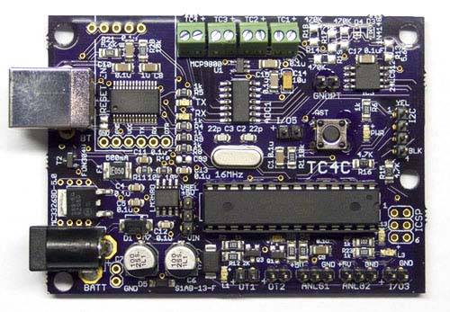
In a week or so, a new option will be available in the TC4 system. The "TC4C" (TC4 Complete) is part Arduino, part TC4. This is a standalone system that provides the same capability as an Arduino board with a TC4 shield attached. It is fully Arduino-compatible (it has Uno firmware, but uses the well-known FTDI USB-serial interface). The TC4C will be available with a choice of software pre-loaded, so there will be no need for end users to use the Arduino IDE to configure their boards. Jim
JimG attached the following image:
Edited by JimG on 10/23/2011 8:42 PM |
|
|
|
| JimG |
Posted on 11/01/2011 9:54 PM
|
|
1 1/2 Pounder Posts: 834 Joined: October 23, 2008 |
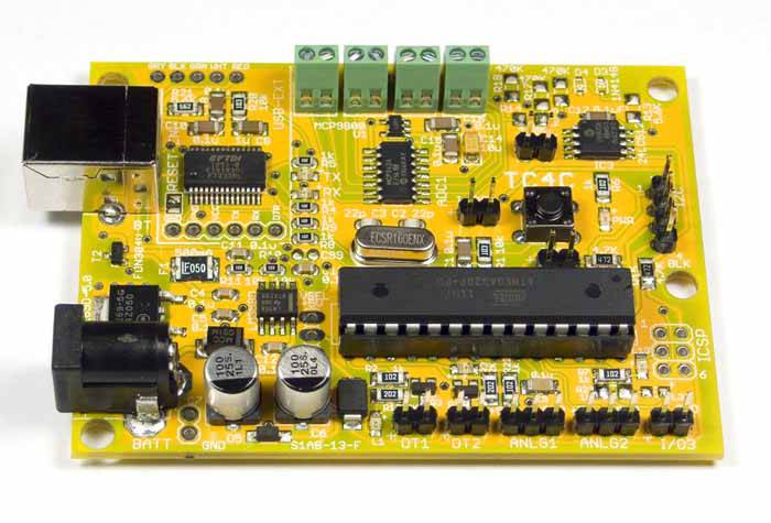
The TC4C boards are now available. The TC4C was designed with the person in mind who does not wish to buy an Arduino board and then install/learn the Arduino programming IDE. So while the TC4C is compatible with the Arduino Uno, and can be reprogrammed using the Arduino IDE at any time, I will ship them out pre-programmed with aBourbon, aCatuai, aArtisan, or (new for the Quest) aArtisanQ. A few other whistles and bells were added (like a place to connect a Roving Networks Bluetooth adapter, sockets to allow panel-mounting the USB connector, and optional sensor-break detection). I haven't checked to see if Kona will fit on the TC4C, but if it fit on an Uno then it will fit on the TC4C. A little more information about the TC4C is on the project's open source googelcode site here: http://code.googl...c4-shield/ Schematics and board layout are here: http://tc4-shield...TC4C/V1.10 Jim
JimG attached the following image:
Edited by JimG on 11/01/2011 9:58 PM |
|
|
|
| JimG |
Posted on 11/20/2011 11:45 AM
|
|
1 1/2 Pounder Posts: 834 Joined: October 23, 2008 |
Finally getting around to starting some documentation for the TC4 system. My first effort is this sample wiring diagram that shows how a roaster with an electric heater and AC fan can be controlled using the TC4 system. This example uses phase angle control (like a router speed controller or light dimmer) to control the AC fan. In addition to a TC4 shield or TC4C board, this requires a random fire SSR (like Crydom D2425-10 or similar) and a zero crossing detector (ZCD) for the AC power. I now have the little (1" x 1.5") ZCD boards available -- cheap. The heater is controlled using pulse width modulation (PWM) with a standard SSR (i.e. Crydom D2425 or similar). The sample wiring diagram also shows how potentiometers can be added to provide manual heater and fan output control, as well as how an LCDapter with 4 pushbuttons and LCD panel can be added. For the beta aArtisanQ application, neither the potentiometers nor the LCD panel are required. Both the heater and the fan can be controlled directly through Artisan's custom event buttons. Link to sample wiring diagram: http://www.mlgp-l...111120.jpg Jim |
|
|
|
| Bhante |
Posted on 11/24/2011 11:59 AM
|
 1/2 Pounder  Posts: 228 Joined: February 13, 2011 |
Quote JimG wrote: The TC4C boards are now available. Are you offering bare boards for the TC4C and the zero crossing detector? I have a couple of suggestions for the next versions: (1) The little screw terminals for the thermocouple connectors are not very secure, and I find they come undone very easily. I think some kind of cable binding is required for the thermocouples. A very simple but effective solution is simply to put one hole about 0.5 - 0.8 mm diameter on either side of the thermocouple cable as it comes out of the screw terminal. Through these two holes a little nylon fishing line (or similar) can be threaded through the two holes and tied around the cable - I did this here:  (2) I find that putting the thermocouple connectors where they are on the TC4 (i.e. on the USB socket side) is not ideal, as the cables then (for me at least) have to be bent round 180 degrees, and with too much fiddling the cables soon come loose from the connectors. The TC4C looks like an improvement on this. Better still would probably be the opposite side from the USB, but maybe that is inconvenient for the circuit layout, in which case the top side (as in the TC4C) is an acceptable alternative. (3) What about finding a solution to the problems of the I2C sensitivity to noise? Something to help stabilise the voltage, like a voltage regulator? A schottky diode for supressing transients, or some other transient protector? Screening the cable to the LCD (although mine is very short, not sure that it would help much in my case)? I like the relocated I2C connector by the way, you might like to put the (throughpin) I2C connector on the LCD adaptor on the edge also if you do another version of that. I like the idea of combining the arduino and the TC4 on one board, I think that makes a lot of sense and should be much easier to find a suitable small box that fits. I see you used the DIL version of the CPU rather than the SMD version - probably for ease of programming the bootloader? Bhante Edited by Bhante on 11/24/2011 12:03 PM |
|
|
|
| JimG |
Posted on 11/24/2011 4:13 PM
|
|
1 1/2 Pounder Posts: 834 Joined: October 23, 2008 |
Quote Bhante wrote: Are you offering bare boards for the TC4C and the zero crossing detector? Yes, if you would like. Lately there has not been much interest in bare boards, so I did not list a bare board option for the TC4C. I'll update the ordering page to include both TC4C and ZCD boards. Jim |
|
|
|
| Bhante |
Posted on 11/24/2011 4:24 PM
|
|
1/2 Pounder Posts: 228 Joined: February 13, 2011 |
Quote JimG wrote: Quote Bhante wrote: Are you offering bare boards for the TC4C and the zero crossing detector? Yes, if you would like. Lately there has not been much interest in bare boards, so I did not list a bare board option for the TC4C. I'll update the ordering page to include both TC4C and ZCD boards. Jim That's good. (I won't be ordering for the time being anyway though, because I currently have far too much on my plate!). |
|
|
|
| JimG |
Posted on 11/24/2011 4:25 PM
|
|
1 1/2 Pounder Posts: 834 Joined: October 23, 2008 |
Quote Bhante wrote: I have a couple of suggestions for the next versions: (1) The little screw terminals for the thermocouple connectors are not very secure, and I find they come undone very easily. I think some kind of cable binding is required for the thermocouples. A very simple but effective solution is simply to put one hole about 0.5 - 0.8 mm diameter on either side of the thermocouple cable as it comes out of the screw terminal. Through these two holes a little nylon fishing line (or similar) can be threaded through the two holes and tied around the cable - I did this here: I'll look into this and see if there is enough real estate in front of the connectors. I like the idea. Quote Bhante wrote: (2) I find that putting the thermocouple connectors where they are on the TC4 (i.e. on the USB socket side) is not ideal, as the cables then (for me at least) have to be bent round 180 degrees, and with too much fiddling the cables soon come loose from the connectors. The TC4C looks like an improvement on this. Better still would probably be the opposite side from the USB, but maybe that is inconvenient for the circuit layout, in which case the top side (as in the TC4C) is an acceptable alternative. I appreciate the inconvenience, but moving the terminals on the shields will be close to impossible. Keep in mind that the top and bottom sides are taken up by the Arduino stacking headers. The current design (5.20) uses all of the available space on the right side for I/O ports. This leaves only the left (USB) side for the thermocouples. Quote Bhante wrote: (3) What about finding a solution to the problems of the I2C sensitivity to noise? Something to help stabilise the voltage, like a voltage regulator? A schottky diode for supressing transients, or some other transient protector? Screening the cable to the LCD (although mine is very short, not sure that it would help much in my case)? I like the relocated I2C connector by the way, you might like to put the (throughpin) I2C connector on the LCD adaptor on the edge also if you do another version of that. The next things to try for creating better noise immunity, I think, would be to try twisted cabling, or maybe even shielded. Stronger pullup resistors (i.e. smaller resistance values) on SDA and SCL might help, too. It is not clear to me if the problem is related to the SDA / SCL signals, or if it is a Vcc problem. The newest rendition of the LCDapter (made to fit the TC4C) features a direct pin-to-header connection and eliminates the cable requirement (a cable can still be used if desired, though). It will be interesting to see if this makes any difference. I don't know how common the I2C glitches are. I never see it on my roaster or other applications. I only see it about once a month on my Silvia espresso machine. It could even be a software issue?? Jim |
|
|
|
| Bhante |
Posted on 11/24/2011 4:56 PM
|
|
1/2 Pounder Posts: 228 Joined: February 13, 2011 |
Quote JimG wrote:I don't know how common the I2C glitches are. I never see it on my roaster or other applications. I only see it about once a month on my Silvia espresso machine. Oh!!! I get it daily! The gobaldygook that you have many times described I have very occasionally seen, but only I think in relation to connection problems, or sequence of connection (LCD after reset) etc. Apart from that I think I have seen it about once on my espresso machine. But I regularly experience problems where it hangs, on my espresso machine (where it is connected all day). So much so, that I now invariably reset it before pulling a shot, if it has been on for a while already. Transients from the heater switching would make most sense to me. However I have also had the problem in identical form when just connected to my computer, well away from the espresso machine, particularly if it is on for some time. What I observe is that the display looks fairly normal (apart from the displayed time, which is sometimes 59:59 and sometimes a very large number), but the temperatures displayed do not change, and are fixed on whatever it displayed at the time it hanged. Judging from the times it occured while attached to the computer, I think the serial data also freezes, but of course I cannot say with absolute certainty that it is exactly the same error as with the espresso machine. I think I had more problems earlier while I was using a different (USB) power adaptor for the Arduino on the espresso machine, which I suspect was a bit tight on the juice. That adaptor died, and since I replaced it with a better quality one (one of these small iPhone USB adaptors from China) it's been running better. Of course it may be that it has nothing to do with the I2C connector. |
|
|
|
| Bhante |
Posted on 11/24/2011 4:58 PM
|
|
1/2 Pounder Posts: 228 Joined: February 13, 2011 |
Quote JimG wrote:I'll look into this and see if there is enough real estate in front of the connectors. I like the idea. 2 mm is better than nothing if space is really limited, though 4 mm is of course very much better. Edited by Bhante on 11/24/2011 4:59 PM |
|
|
|
| JimG |
Posted on 11/25/2011 4:49 AM
|
|
1 1/2 Pounder Posts: 834 Joined: October 23, 2008 |
Which application is running when it hangs? Perhaps there is a memory leak and the 2K RAM limit is being exceeded. Jim |
|
|
|
| Bhante |
Posted on 11/25/2011 5:35 AM
|
|
1/2 Pounder Posts: 228 Joined: February 13, 2011 |
Quote JimG wrote:Which application is running when it hangs? Perhaps there is a memory leak and the 2K RAM limit is being exceeded. It is running aCatuai. Memory leak? Is that a water leak or a coffee leak, like the dark brown drips that sometimes come out the back of the hottop? I'd hate to think of the CPU getting clogged up with sticky coffee inside the chip! Bhante PS - Quote JimG wrote:Posted on 11/25/2011 03:49 Are you always up so early Jim?? Edited by Bhante on 11/25/2011 5:38 AM |
|
|
|
| JimG |
Posted on 11/25/2011 6:02 AM
|
|
1 1/2 Pounder Posts: 834 Joined: October 23, 2008 |
Quote Bhante wrote: PS - Quote JimG wrote:Posted on 11/25/2011 03:49 Are you always up so early Jim?? That is a little before 6:00 am here, so I am usually up. Functioning is another matter :| Jim |
|
|
|
| Coffee makes the world goround |
Posted on 12/10/2011 5:28 AM
|
 Newbie  Posts: 49 Joined: December 12, 2010 |
HI  i have question i have question the kit , is the IC already programmed , meaning that if one did buy one and finished it , it would be the same as the TC4C or can one programme it without a ardino board i have a friend that is into electronics , and he thinks he can do it , he has the equipment to program IC`s , and make his own programs and prototypes etc i only want to monitor and log the roasts , not control the roaster but better have it (that function),and not need it , than (later )needing it and not have it  i dont see the need for a (expensive) meter , just to feed the PC with the temp info I live in Denmark , but might have some come over in Christmas , that could bring me one along |
|
|
|
| JimG |
Posted on 12/10/2011 12:01 PM
|
|
1 1/2 Pounder Posts: 834 Joined: October 23, 2008 |
Quote Coffee makes the world goround wrote: is the IC already programmed , meaning that if one did buy one and finished it , it would be the same as the TC4C No. The TC4 shield does not have a microprocessor on board, so there is no IC to program. The shield just provides an interface between the Arduino and a few thermocouple sensors, SSR's (optional), and LCD display (also optional). All of the programming is done to the ATmega chip on the Arduino. The TC4C has all of the shield hardware, plus the ATmega328P microprocessor, so it can stand alone. The TC4 shield cannot stand alone and must be attached to an Arduino. Jim |
|
|
|
| Coffee makes the world goround |
Posted on 12/10/2011 1:40 PM
|
|
Newbie Posts: 49 Joined: December 12, 2010 |
DOHH now i get it I did just look at the pictures of the boards ,that was on the ordering page they did all look the same but after clicking the link at the TC4C i could see the different board well and after looking at the Typical wiring diagram for roaster control using TC4 system. it looks like it can get its power from the usb cable ..is that right ?? so a TC4C + a usb cable + (up to 4)K type probes download artisan and i should be good to go ?? Is the TC4C only sold as a completely build , or , are they sold as kits too ? |
|
|
|
| JimG |
Posted on 12/10/2011 7:22 PM
|
|
1 1/2 Pounder Posts: 834 Joined: October 23, 2008 |
Quote Coffee makes the world goround wrote: it looks like it can get its power from the usb cable ..is that right ?? so a TC4C + a usb cable + (up to 4)K type probes download artisan and i should be good to go ?? Yes, that's all correct. Quote Coffee makes the world goround wrote: Is the TC4C only sold as a completely build , or , are they sold as kits too ? I've not offered them as kits mostly because I thought most people would want something that worked right out of the box. If you built the kit yourself (which would not be very hard), then you would still have to download and install the Arduino IDE and program the board yourself. And then there is the issue of writing documentation, something I am famously bad at doing. Jim |
|
|
|

| Jump to Forum: |
Powered by PHP-Fusion Copyright © 2024 PHP-Fusion Inc
Released as free software without warranties under GNU Affero GPL v3
Designed with ♥ by NetriXHosted by skpacman