
Login

Shoutbox
You must login to post a message.
renatoa
07/26/2024 3:49 PM
Bill grubbe and Jk, 
allenb
07/26/2024 5:15 AM
Spiderkw Welcome to HRO!

renatoa
07/24/2024 8:31 AM
ramiroflores and John123,

 ?
?
?renatoa
07/21/2024 1:18 AM
 , Luislobo
renatoa
07/19/2024 11:28 AM
Koepea,
Forum Threads
Newest Threads
Skywalker roaster modsBackground Roast Iss...
Hello from Arkansas
TC4ESP
Green coffee reviews
Hottest Threads
| Skywalker roaster... | [375] |
| TC4ESP | [115] |
| War on Farmers by... | [47] |
| Adventures in flu... | [26] |
| Hello! (soon) Roa... | [17] |
In Memory Of Ginny

Donations
Latest Donations
dmccallum - 10.00
JackH - 25.00
snwcmpr - 10.00
Anonymous - 2.00
Anonymous - 5.00
dmccallum - 10.00
JackH - 25.00
snwcmpr - 10.00
Anonymous - 2.00
Anonymous - 5.00
Users Online
Guests Online: 7
Members Online: 0
Total Members: 8,393
Newest Member: Bill grubbe
Members Online: 0
Total Members: 8,393
Newest Member: Bill grubbe
View Thread
Who is here? 1 guest(s)
 Modifying the Poppery 1
|
|
| Mike |
Posted on 05/29/2006 4:35 AM
|
 1/2 Pounder  Posts: 283 Joined: October 24, 2005 |
MODIFYING THE ORIGINAL POPPERY P1 1-1  Hi! My name is Mike and I am a committed (or committable) Home Coffee Roaster Geek. I take it that since you are here you may fear (or know beyond a shadow of a doubt) that you have a propensity toward this malady. Or then again you may be perfectly normal without these debilitating genetic defects, and just be interested in Homeroasting your own coffee. If you actually meant to get to this location, and are not caught up in the sharp wind that I just felt as people evacuated the premises, then read on. Once you?ve gotten a feel for the place ? be sure to leave some comments in a post at the end of the thread. As long as you don?t get too personal I promise to take the comments seriously and hope that among us we can turn this into a better article. The focus of this series of articles is to: step by step our way through modifying (for coffee roaster use) the West Bend ?The Poppery? (P1). This popcorn popper is the ?Grand Old Man? of hot air coffee roasters with a distinguished history of home use. This series of articles will take you from ?Baby Steps? all the way to some truly sick levels of Geeky enthusiasm. The modifications addressed in this first article are applicable to other popcorn poppers (with minor changes to size of can etc.) as well as the P1. In the interest of engaging everyone who visits this thread we?ll try to keep things as simple as possible with as little multi-syllable geek talk as possible. In your review of the work keep a look out for easier more understandable ways or explaining things ? and let me know in a follow-on post to the thread. And for those accomplished Home Roasters out there that are only reading this for entertainment value ? You really need a life ? but in the meantime your experience and expertise will be appreciated and valuable to the article, if you?ll share it with us in (you guessed it) a follow-on post to the thread. I hope I?ve established a pattern here ? If you will get involved with this ? we should be able to provide the new Home Roaster with a single location resource, and have a little fun in the process. Before committing yourself to a ?full course? of popcorn popper modifications, you should ask yourself if a roaster with the limitations inherent to the popper is what you really want. I?m sure someone will come up with some more limitations but the below listed ones will probably be the deal maker / breaker for most folks that are relatively new to home roasting. Hot air (technically fluid bed) roasting in less than seriously modified poppers exhibit a ?brightness? in the coffee that some adore and some dislike. This artifact can be minimized in several ways ? the major technique being to control the heat to extend the roast from the 5 or 6 minutes to full roast without heat control, to 12 to 14 minutes with heat control. Many people contend that the longer roast results in a smoother taste more to their liking. Another technique that some people are convinced provides a more complete flavor is limiting the amount of air flowing past the beans to the minimum amount necessary to produce enough bean circulation for an even roast by controlling the speed of the fan. The size of the roast is another shortcoming of the less than fully modified popper. Around a half cup (85 - 90 grams) of beans (maybe a little more) is about the limit until an appropriate chimney (to increase the roasting chamber volume) and fan speed control (to circulate a heavy load of beans during the initial drying stage of the roast) are implemented. These modifications along with tilting the roaster (to lower the required fan pressure necessary to move the beans on the high side of the tilt) will allow the P1 to roast a green bean load of up to approximately 260 grams. The one shortcoming of the popper based roaster that hasn?t been solved yet is the noise generated by the fan. The noise may make it difficult to hear the beans second crack. Some people don?t seem to have any trouble hearing it and others decide to roast by color and time rather than relying on the sound for an indication of roast progression. Again, a partial solution to this can be implemented while modifying the roaster with the judicious use and placement of insulation to provide some sound deadening. The P1 was picked as the subject for these modifications for several reasons - the first of which is: That I have some experience with this model, and there is a wealth of information from other sources concerning its modification. The second reason is: the P1 was built during a time when ?throw away? appliances were not the norm. It uses a die cast aluminum roasting chamber, a simple nichrome heater with an over temperature thermostat and a fairly rugged and long lasting 120 volt fan. All (that I am aware of) of the more recently built poppers use a low voltage DC fan motor with a portion of the heater element acting as a resistor to drop the voltage to whatever is appropriate for the motor, with diodes to pull the necessary DC current from the 120 V power that powers the popper. This decision to make the P1 the subject of this article, in no way is meant to lead anyone to believe that other poppers are not perfectly adequate to develop into a roaster or use as one "out of the box". They do work and with modifications, that are specific to them and not necessarily the same as those for the P1, can do a superb job as a roaster. Other threads and articles will be started and written to deal with these machines. The third reason is: Size. The P1 has a substantially larger roast chamber than the more recent generation of poppers, and can only be matched by a couple of other popper models of approximately the same vintage as the P1. This size translates into a green bean load in a fully modified P1 based roaster of up to approximately 9 ounces which nets 1/2 pound of roasted beans per roast. The final (for now) reason: Is availability. The P1 was by far the most commercially successful Hot Air Popcorn Popper of its day. P1's are commonly found at thrift and 2nd hand stores and currently, the P1 is always available on eBay. EBay costs fluctuate from $10 to $35 plus shipping, of course. Thrift and 2nd Hand store prices are usually considerably cheaper - less than $5. I've never paid more than $4.50 for the dozen P1's I've purchased at thrift stores; I've paid as much as $40 ($30 cost plus $10 shipping) on eBay. The roaster that can be produced using the P1 should be an appliance with a virtually unlimited lifetime. Repairs, when necessary, should be easily accomplished and the current availability of the P1 should supply whatever repair parts are necessary. By all means pick up a couple of extras to squirrel away in the garage (I have), because the availability could change dramatically in the future. My roaster has served me well for several hundred roasts without a hiccup. You are still reading - you must have decided that this is something you might want to try. I?ll start out by explaining how this series of articles is going to be laid out. You may have noticed that there is a thread ?Modifying The Poppery 1? in the discussion forums of this site http://homeroaste...ead_id=270 this discussion forum is intended to be an interactive method for you to participate in this endeavor. Hopefully we will be able to have an active discussion of these articles and generate some new content for them or even re-write what is in them currently. The P1 has been around for quite a while and has been used as a coffee roaster for a large portion of its existence. I?ve been modifying these things for a relatively short time as compared to some folks. I?ve benefited from a lot of noodeling, experimentation and experience by and from these people. I hope we can attract some of these folks to the discussion forum. If this experiment works, these articles and the supporting thread should become the resource for the newcomer to popper roasting as well as those that want to get a little more out of their current equipment. I hope you all got out of the previous statements that I am in no way presenting myself as the ?fount of all knowledge? regarding popper roasting. So - Let's get started. The first thing you'll need obviously is an original West Bend Poppery: P1 1-2  The two machines in the picture are the original P1 (left) and the West Bend Poppery II (right). If you are shopping for your machine on eBay - look over the picture to be sure you are buying the correct model. The P1 brings a better price and some unscrupulous sellers try to sell the P II as a P1 and I have seen pictures taken from a vantage that can fool you. If you have never handled either machine and don't have a copy of the picture in your pocket when you stop by the local Salvation Army - remember the P1 has a power switch in the lower right portion of the label. The P II does not have a power switch. After you've handled these two machines once, you won't mistake them again. The P1 is considerably heavier as well as physically larger. I have never personally seen a sub-1500 watt P1, but I have heard that there are a few of them out there. You may want to turn the P1 over and look at the information on the base to be sure it is a 1500 watt unit. The picture of the two poppers does not include the plastic cap and butter dish on either machine. These pieces are unnecessary for our uses. Seeing as how I brought a little history into the conversation a little earlier, we?ll start getting our hands dirty with the earliest modifications and work toward the current state of the art. We will try to accomplish these mods in a piece-meal fashion that shouldn?t leave you without a roaster for any length of time. Each modification or group of modifications should take no more than a couple of hours. Be sure to read completely through each modification and be sure you have whatever tools and supplies are necessary prior to starting. For many of the modifications there isn?t really a cook-book way of accomplishing them. Rather you will find that there will usually be several ways to accomplish the desired outcome. As we progress into the more complex modifications you will be dealing with circuits that carry a substantial amount of power and if it is not dealt with respectfully it can hurt you. Respectfully is a really soft way of saying ? If you are uncomfortable with anything you see in the articles ? STOP ? go to the discussion forum and query the folks that are on there to make sure you understand exactly how to proceed. If you are still uncomfortable, don?t attempt the modification by yourself ? get in contact with someone who you are confident is capable of dealing with the mod and have them step by step you through it. Don?t let you?re ego drive you ? we all had to start somewhere and having a knowledgeable person tutor you (it usually just requires an easy explanation) is always a worthwhile experience. If you find that you require some tutelage outside of the articles and forum ? BE SURE ? you bring it up on the forum and work through how the awkward portion of the mod was explained and accomplished. With this kind of feedback we?ll be able to tune up the articles to better serve the next person attempting the mod and the community in general. At some point I may have to do the preceding paragraph is bold large typeface underlined in red. Bean Volume, Ventilation and the Beginning of Heat Control. We are going to get our feet wet by increasing the volume of beans that the P1 is capable of roasting. This first set of mods will allow roasting half again more beans that it can do in its ?out of the box? condition. We will increase the roast chamber volume with a tin can. We will talk about how to keep the rest of your family a little happier by figuring out a way of keeping the kitchen from becoming a dumping ground for the chaf generated by the roasts. We will also try a couple of simple tricks to lower the voltage to the roasters heater and thereby lengthen the roast a bit. First step is to go to the pantry with your P1 firmly in hand, try inserting several different sized tin cans into the throat of the P1 to identify the right size to use for a chimney. It will not be difficult to find the right size that seems just a hair too large. P1 1-3  You will probably be well advised to check with the meal planning member of the household about what to open and store the contents in the refrigerator for a future meal. My can opener is one of those that un-crimps the seal around the can so your can may not look exactly like mine. After removing one end, emptying, removing the label and washing the can - remove the other end so you have a hollow cylinder. This would probably be a good time to be wearing some thin leather work gloves. BE CAREFUL - don't cut yourself on the sharp edges. Use a small piece of fairly course emery cloth or sandpaper to clean up any sharp areas on the edges of the can after removing any small sharp shards of metal left by the can opener. Set the can aside. In some cases ? if the can is exactly the right size ? you may find that the can will (with a little pressure) fit without modification. You should be going for an interference fit that will not result in the can falling out at an in-appropriate time and depositing hot beans all over you and your roasting location while emptying the roaster. This will not only waste beans but could result in burns and blisters to your body. If you look down into the throat of the P1 you will notice a "fin" running vertically from the top down toward the roast chamber. In the P1s previous life as a popcorn popper this fin was useful in directing the popcorn straight up and out of the popper. P1 1-4  I have a "nibbler" that removes a "slot" of sheet metal but this is not necessary. A pair of diagonal wire cutters, sheet metal shears or even a carefully manipulated hack saw blade can be used to make a cut in the tin can. Remember ? wear gloves ? the cut edges are sharp - dress up the edges with emery paper or something else to dull them down after the cut. P1 1-5  You have already noticed that, in these pictures, the lower chimney throat piece of the P1 has been removed. I did this is to make it easier to see what is going on - it is unnecessary for this method of accomplishing this modification. The tin can may now be inserted into the throat of the P1 and "seated" with the slot in the can registering with the fin in the throat of the P1. The slot in the can should deform around the fin and may need to be slightly bent against the inside of the throat with a screwdriver or some other tool extended down inside to reach it. If the can is "seated" with enough pressure, it will stay in place and be quite stable. The chimney mod - looking up from the roast chamber should now look like this: P1 1-6  The chimney mod is now completed. Ready to roast! Another way of accomplishing this mod is to remove the fin from the inside of the original bakelite. So as not to fill up the P1 with the remains of the fin, removing the upper throat section should precede the destructive portion of the fin removal. P1 1-7  A couple of tools necessary for this are: a medium sized Phillips screw driver to remove the three screws holding the upper bakelite chute and a "nut driver" or a similar small socket arrangement, the size of the fasteners is 1/4". Screwdrivers with removable bits are usually 1/4" internal hex and will also work. P1 1-8 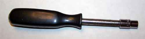 Reach down into the P1 with your tool and remove the two fasteners (Red arrows in the following picture) holding the Bakelite chimney section in place. P1 1-9  Once this chimney section is removed, the fin (green arrow in the preceding picture) can be attacked with whatever instrument of destruction (pliers followed by rasp, file, dremel tool with a drum sander installed) you want to use. Once the fin is removed and the throat is smoothed, reassemble the P1 and press in the tin can chimney - the slot in the bottom of the chimney is no longer needed if you decide to use this method. This may have been baby steps, but we have at least started the journey. P1 1-10 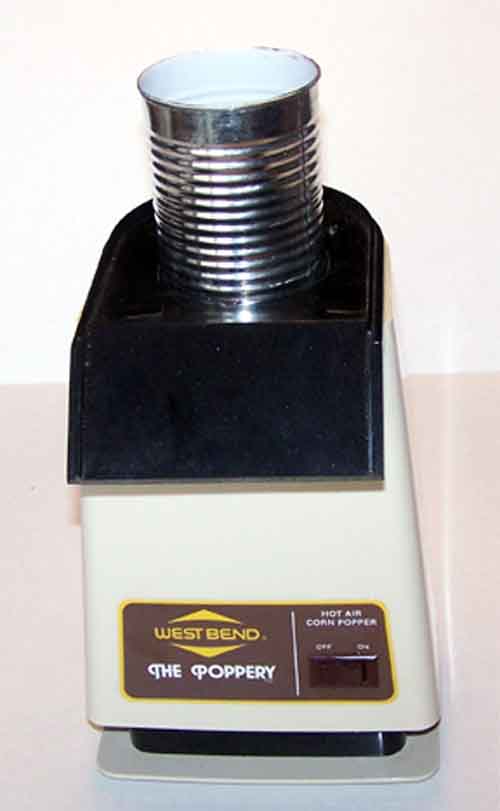 Ventilation As I mentioned at the beginning of this article - we'll get you started toward keeping your roasting environment clean enough to live with. When roasting coffee beans they lose their "silver skin" (called chaff) which is an extremely light skin layer on the bean that is light and fluffy and while roasting it gets all over everything nearby. Commercial roasters use large cyclone separators to remove the chaff from the exhaust air stream. Lacking this piece of equipment we'll try another approach. The easiest most effective method available to us is to just get it outside and let the wind deal with it - it decomposes into the environment quickly and harmlessly (in fact it is good for your garden - as well as the coffee grounds that are produced at the other end of our obsession). We are left with the options of: roasting outside, or routing the exhaust from the roaster to the outside. Roasting on the deck is a nice relaxing way of spending a little time outside with a beverage of your choice and your dog at your side. And for a substantial portion of the year this idyllic setting may be your choice. Here in Oregon there are seasons when the deck is just not a comfortable choice. As well as the fact that the lower the ambient air temperature that you roast in, the more heat that is required from the roaster, this starts to complicate things. Your local hardware store is about to make your life more comfortable. We can build something roughly based around the artifact in this picture: P1 1-11 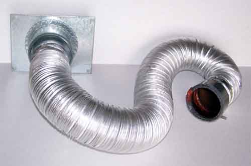 This particular setup is what I use to vent through the ventilation hood over my kitchen range. Before trying this solution, you need to be sure that the fan in your ventilation hood is capable of passing chaff through. Some ventilation hoods use squirrel cage fans with small slots in the squirrel cage that will trap the chaff rather than blowing it through the exhaust path. If you would rather not use the ventilation hood - exhausting through a partially open window with a similar piece of the metal flexible ducting works well also. This ducting is usually available at your local big box store such as Home Depot for $6 to $7 for a piece that is plenty long enough when un-collapsed (it is packaged collapsed). There are several different sizes available - the size that is slightly larger than 3 inches Inside Diameter is what I use. If the ventilation hood over your kitchen stove exhausts outside, the fan will pass chaff and the ducting run from the hood to the outside is not too long, you may decide to copy the one I use. If this is your decision - look under the vent hood and you should see something similar to this: P1 1-12  You'll see one or two expanded metal grease filters that are easily removed by sliding first one way then the other (forward - drop one end a little - backward, and the filter is out). Yes they are greasy and need a lot of detergent to clean. After a little elbow grease and detergent it probably looks similar to this: P1 1-13  This next picture shows a couple of sheet metal fixtures with which I terminated the ends of the flexible ducting. P1 1-14 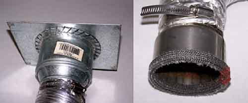 The circular one on the right is a pretty standard size that can be procured at most stores that handle ventilation pieces and parts - such as Home Depot. The particular one I use is stainless steel with some wood stove door gasket material held in place with RTV (definitely un-necessary) from a wood stove store. The High Temp RTV is available at most auto parts stores as "Permatex High Temperature RTV Gasket Maker", it is also sold under similar descriptions with other brand names. In fact, the easy thing to do at the roaster end of the duct is to just push it over the chimney (without a fixture). Running the ventilation fan in the hood will just suck a little extra air around the chimney and cool the roasters exhaust before getting into the fan - this is not a bad thing. The other square fixture I had built at the local heating and air conditioning shop for $7. I took the filter (cleaned) to the shop dropped it off, explaining what I wanted and had my fixture a few hours later - I'm not sure if the price is normal or if I just got a good deal because I'm such a sterling guy. A fixture such as this can be sized to fit into a partially open window (close the window on to the fixture) to exhaust directly outside and keep the winter (and flying chaff) out while roasting. P1 1-15  As you can tell from the pictures both fixtures are fixed to the ends of the flexible ducting with hose clamps from, you guessed it, Home Depot (also available from any auto parts house). In the interest of keeping the ventilation path relatively un-obstructed and safe from grease fires etc. - It is important to do a regular vacuum of the areas around the filter opening in the hood. After a roast you will see something like this: P1 1-16 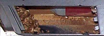 I vacuum (with the hose hooked to a stand up floor vacuum) after every roast - just takes a minute. Before re-installing the filter which I've replaced with my vent rig while roasting, I remove the other filter and vacuum inside both filter openings. The ventilation path from the vent hood to the outside at my house is less than a foot - so you want to take this into consideration when deciding if the amount of chaff and debris left in the ventilation path could present a problem for you. For those of you lucky enough to have a kitchen range with working surface level ventilation such as the "Jenn-Air" check out jimoncaffeine's solutions to roasting ventilation: P1 1-17 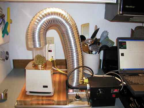 And I believe this is Jim's current solution: P1 1-18  Notice the stainless steel measuring cup wedged under the side of the roaster facing the camera. I use the same technique to promote circulation in my P1 roaster (although mine is not as classy - it is a cheap plastic one). This technique angles the roast chamber and leaves one side of the bean load lower than the other, this requires less pressure from the fan to initiate bean circulation. Using the glass chimney makes the benefit to circulation resulting from this tilt clearly visible. It will allow a larger initial green bean load (when the heavier beans are more difficult to circulate). We'll get to chimney modifications in a latter article. So we don't lose track of the reason we are all doing this, the following picture is probably 7 minutes (including a couple of minutes cool down) after the 373? showing on the PID in the previous picture: P1 1-19  Heat Control This final section of the initial chapter on P1 modifications will not deal with the Popper at all, instead we will deal with the power supplied to it. As we?ve already talked about, there are several variables in the roasting process that we are trying to gain control over. In follow-on chapters we?ll figure out ways to actually manipulate these variables in real-time while roasting and use that ability to manipulate the ?profile? of our roasts. In a roasting process the amount of heat the bean mass is subjected to, is a major consideration and therefore we would like to, even at the rudimentary modification level that we are currently at, address it. We will manipulate it a little to benefit the quality of our roast. The heater section of the P1 is a simple length of coiled nichrome wire that, when energized from your houses wall receptacle, gets red hot. The heat is transferred to the air flowing past it and then transferred to the bean mass in the roast chamber. Nichrome wire changes it?s resistance to current flow as it?s temperature changes and exhibits a little tendency toward self regulation. Not enough self regulation to keep it from burning up if the heat isn?t removed by the air flow. A thermostat that unhooks the circuit (opens it) from the line power when the temperature increases to the set point of the thermostat and protects the nichrome heater element from self destruction upon loss of air flow (fan kaput) . We are going to deal, directly, with this thermostat in a future chapter in this series. If we can manipulate the voltage of the power supplied to the heater we can change the heaters heat output. There is some math involving resistance, voltage and amperage that we could throw at this problem to quantify the how and what of this to go along with the why that we have already discussed. Let?s not get involved in the math; we?ll accept that these things work that way and move on to manipulating them. If we increase the resistance in an electrical circuit we decrease the current flowing through it, like increasing the resistance to water flow in your garden hose by closing the water valve a little ? the water flow decreases. As in this example the amount of current (amperage) flowing through a wire can be changed by making the circuit more resistant to the current flow. A longer or smaller wire will present more resistance to this current flow. If measured at the load end (heater/fan) of the wire you will see a decrease in voltage when the circuit is under load (turned on) as compared to the same circuit without the longer or smaller wire in the circuit. A long winded way to get to here ? we are going to power your P1 through an extension cord. The reason I?ve gone through all of this is to make sure you consider possible results of what we are doing. Why is this important? If not accomplished correctly (you using your head) you could establish a condition that will blow the breakers in your electrical distribution panel at the least and cause a fire at the worst. You need to understand what you are doing, so a little more explanation is appropriate. The resistance to current flow by using an extension cord will result in heat (power) being lost in the extension cord. If I use a short piece of thin (small gauge) wire, that heat will be concentrated in the short length of the wire. If this is taken to an extreme (smaller and thinner wire) it can result in enough heat to melt the insulation on the wire and cause shorting of the circuit and in a worst case, a fire could result. On the other hand, if I use longer and larger (big gauge) wire, the heat will be lost in a larger area so less heat up of any given portion of the wire will be observed. By the way, wire gauge is measured in a counter intuitive fashion ? bigger numbers mean smaller wire. So 20 gauge wire is smaller (will get hotter in our circuit) than 10 gauge wire (cooler in our circuit). What we are going to accomplish with the extension cord is lowering the voltage that the heater (coiled nichrome wire) sees in the circuit. To lower the voltage a given amount in an otherwise unchanged circuit we need to present resistance to that circuit. I can present that resistance with a short small gauge wire or with a long large gauge wire. The circuit (the P1) doesn?t care which way we decide to accomplish the addition of this resistance, the results will be the same. This (possibly overly pedantic) explanation is my argument for using a long, large gauge extension cord rather than a short, small gauge one. The following picture shows (on the left side) a valuable piece of safety equipment for anyone who is manipulating electrical circuits ? a ground fault interrupter that will open the circuit (turn it off) at the first indication of a short. The picture also shows (on the right side) several different types of extension cords. P1 1-20 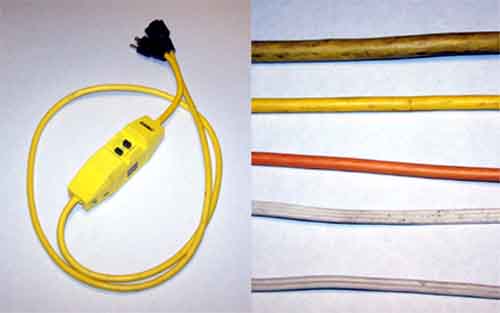 I strongly advise and argue for the use of the Ground Fault Interrupter (GFI). A GFI like this one can be purchased at most any hardware store for the reasonable price of about $15. You need one that is sized to deal with a minimum of 15 amps (mine is a 20 amp unit) when trying to protect yourself and your houses electrical distribution network from the circuit we are playing with. When you use one of these, it must be the final link to your household electrical system. That means that you plug the GFI into the wall receptacle and plug the rest of the circuit (extension cord ? P1) into the GFI. This is cheap protection. I use mine whenever I?m using any substantial load (drill, saw etc.) on the end of an extension cord. The picture shows several different gauges of extension cords. The two small ones are double and triple wire 18 gauge cords ? just because the extension cord has an extra wire and place for a ground lug (the third round blade in a plug or receptacle) does not make it appropriate for our use. The largest cord shown is a section of one I use for an electric welder and is made with 8 gauge wire, larger than what we need. The other two cords are 14 gauge (the yellow, larger one) and 16 gauge (the orange, smaller one). For our use it would take a shorter 16 gauge cord to give a given amount of voltage drop than what would be required for the 14 gauge. The voltage at the wall in your location will be another factor in what specific gauge and length of extension cord will meet your needs. My household voltage at the wall is 123 Volts and doesn?t vary by more than .5 volts under normal circumstances. When I look out my front room window, I am looking at the Columbia River and one of the largest hydro electric dams in the world, there is a good chance that your electrical power isn?t as close as mine. There are places where the voltage may be a full 10 volts lower than what I see at home, the decreased line voltage in these locations will not require as much manipulation (extension cords) to lengthen the roast a few minutes. If I roast with an unmodified P1 using a 100 ft 14 gauge extension cord or a 25 ft 16 gauge extension cord I get similar results (three to four minute increase in roast time). When using the 16 gauge extension cord, the heat buildup in the cord is just barely noticeable by feeling it with a bare forearm. When using the long 14 gauge cord I can?t feel a temperature change in the cord. The safer of the two options is obviously the one with the least heat buildup in the cord. A minimal heat buildup in the cord is a compromise that may be acceptable to some folks and not acceptable to others. The only guidance I can provide is: under no circumstances do we want to have enough heat buildup to compromise the integrity of the cords insulation (think of the cord all coiled up in a pile with no cooling air flow between layers of cord in the pile). Mike B) I guess I?ve put chapter two in the Poppery saga off long enough. I?m hoping that you got enough out of the first part of this ?Modifying the Poppery? series to get you started, or help what you are already doing a little. So, we?ll move on to bigger and better things. This time we are going to address a couple of issues that everyone deals with when roasting coffee, no matter what type of equipment they use. The first of these will be temperature indication. The second is gaining more control over the roasters heat. These modifications will add some ammunition to your campaign of starting to ?profile? roast. A short explanation of what is meant by a "roasting profile" is called for at this point. In the strictest sense a profile is no more than a road map through the roast from beginning to end. Starting a roast and increasing the temperature of the bean mass at a rate of 25? per minute for 6 min would change the temperature a total of 150?. Each similar period during the roast with a different rate of temperature increase is commonly referred to as a "segment" or "ramp" (we?ll use ramp in this article). Commonly used profiles are made up of as little as three or as many as seven ramps. This portion of the roast could be described as the first ramp of the profile and would be followed by more ramps that would progress you through the roast to its culmination. Another ramp could be, stretching the time between 1st and 2nd cracks and is commonly accomplished by "slowing" the profile - lowering the rate of temperature increase to, let's say, 10? per minute for four minutes (a total temperature increase of 40? over 4 minutes). The numbers in my examples above are inconsequential; they are only used to explain the process. The information you should take from this discussion is that a "roasting profile" is a roast process that follows a (usually) pre-determined recipe of changing the heat being added to the bean mass during the roast. Changing the roast profile for a given bean will change the taste of the coffee produced from the beans. "Profile Roasting" is a subject that requires considerably more discussion than I've given it. To profile roast your coffee, a method of identifying the temperature of the beans during the roast and a method of controlling that temperature is necessary. Let?s get back to temperature indication. The first method of identifying the temperatures that are important to you as a roaster is the tell tale cracks, first and second. People have roasted coffee for centuries with no more indication of temperature than hearing the cracks. First crack happens somewhere between 395? and 425? Fahrenheit. The second crack is usually between 435? and 455? Fahrenheit. These temperatures are taking into consideration the wildly varying temperatures indicated by the different methods of measurement and the difference in the beans themselves. The location of the indicator probe in the bean mass, how close it is to the hot air flow (in an air roaster) and a myriad of other factors can affect the indicated temperature. My personal feelings are: that the temperature of the bean mass is what we want to measure and an attempt to limit the measurements to this is worthwhile. It is not unusual for two different machines of the same type with what seem to be identical temperature indication hardware to read 10 or 15 degrees different. We should leave this discussion with the understanding that the indication you get with your roaster will depend upon all of the variables already identified, and may vary substantially from numbers you hear from other roasters. The important thing is for you to get consistent indication ? roast to roast. If another roaster identifies a particular temperature for the beginning of first crack with a particular bean and this is 15 degrees different from what you normally see ? ask what the other guy is seeing for second crack, if the difference is the same (within the ball park), this isn?t unusual. What this will do for you is allow using a profile recommended from another individual by factoring in the difference in temperature indication. There are many different methods of implementing temperature indication in your equipment. The commonly available and relatively inexpensive hardware required include: Direct Reading Thermometer (available from Sweet Marias for <$20): P1 2-1  Thermocouple (TC) and TC probe (available from Omega and many other suppliers - $10 to $25): P1 2-2  TC Thermometer (available from Sweet Marias for <$30) and PID Process Controller including an integrated TC thermometer (available from TTI Global for $130 to $200 depending on options): P1 2-3 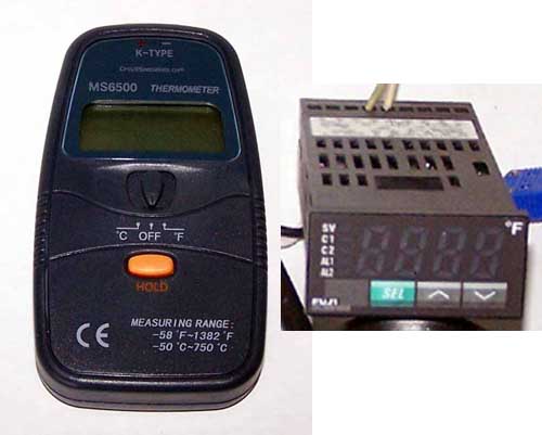 Resistance Temperature Detector (RTD): P1 2-4 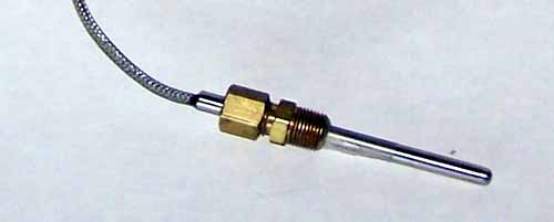 Other methods of temperature detection and indication are available and may work very well for you. If you have experience with one of these, please provide some information in the discussion thread associated with this article xxxx . For the purposes of this particular article we will talk about using a Direct Reading Thermometer and inexpensive TC equipment. The least expensive, easiest to implement of the above options is the Direct Reading Thermometer. Remember from our previous discussion that placing the indicator in the bean mass is our focus. Any method of placing the probe in a location inside the bean mass that can be replicated roast after roast will satisfy our needs. The following pictures show several different methods of accomplishing this. The roast chamber of the P1 is 3 inches in diameter; the horizontal bean mass center is therefore 1 and 1/2 inches in from the wall. The vertical center of the bean mass changes as the volume of the beans changes while they expand during the roast. Identifying an actual vertical center of the bean mass through the entire roast is possible but does not give a consistent location. So let's pick a vertical location for the probe that we can use which will give us consistent information roast after roast. I use 1 and 1/2 inches vertical (from the roast chamber bottom) as well as horizontal (from the roast chamber edge). For those of you who want the quickest, easiest way to implement temperature indication in an otherwise unmodified P1 - the following two pictures should show you how to get there. A hole of the correct size for the shaft of the thermometer you are using is drilled into the center of the butter dish. P1 2-5  A four inch piece of 16 gauge copper wire can be found by removing a piece of wire from some "romex" which is used for household wiring. Bend this wire or something similar around a drill bit or the thermometer shaft itself (be careful not to bend the shaft) a couple of times and twist the ends together with a pair of pliers. Tighten the wire until it has a nice friction fit on the thermometer shaft and can be moved up and down the shaft with a little effort, but will hold the shaft in place without moving on its own. Make two of these friction clips and place both on the thermometer shaft with the butter dish in between. Place this butter dish back on the P1 and adjust the clips to locate the tip of the thermometer in the correct location P1 2-6  This next group of pictures shows a method of installing the same manual thermometer in a P1 modified with a 'tin can' chimney. The small brass fitting can be purchased at any hardware store - this particular size (3/16" ) is used inside plastic tubing when installing a ferrul fitting on it. The tin can is drilled, the brass fitting installed and the can bent at the hole to orient the thermometer into the correct configuration. When everything is in the correct location tape it all securely and use JB Weld to fix the brass fitting in place - DO NOT get the JB Weld on the thermometer shaft (you will want to be able to remove the thermometer). You may want to place a small piece of tape on the inside of the can, where the brass fitting penetrates, to keep the JB Weld from dripping to the inside of the tin can while it is cureing. Of all the commonly available epoxy based adhesives available, JB Weld is the only one I am aware of that will easily withstand temperatures up to 500? without breaking down. The JB Weld must be allowed to cure for 24 hours before using the roaster. A single copper friction collar such as the one used in the unmodified P1 example should be used on the thermometer to position it for depth into the roasting chamber. P1 2-7  This same technique may be used to provide thermocouple temperature indication. P1 2-8  To place the thermocouple (TC) probe into the correct location in this roasters roast chamber, a probe length (shaft only) of 5 1/2" is necessary. Measuring before ordering or making a TC probe is important - each individual application will be at least slightly different. Remember the exact location is not the most important consideration. As long as the probe end is in the bean mass, the important thing is to be able to place it consistently in the same location - roast after roast. I don't think it is necessarily important for people who are considering or implementing any of these modifications to understand the in depth theory behind how a thermocouple works. But a short explanation can clear up a few poor practices which are common among folks that use TC's. Let's start by understanding exactly what is being measured. When two dis-similar metals with particular electron loading in particular orbits of their atoms are in close contact to each other there will be an electrical potential (read voltage) between the two metals. As the temperature changes at the point where these two metals are contacting each other (junction) the voltage will change. If we chart that voltage at different temperatures for the junction of these two metals, we can then use that chart at a later date to identify the temperature at a location of my choice where I place the junction. So - we are measuring the voltage between these two metals (wires) in a meter that is calibrated (using the chart) to read in units of temperature measurement, degrees Fahrenheit or Centigrade. A requirement of the TC indication circuit is that it includes a "reference junction" of the same metals as are being used in the TC. In the "old days" this reference junction was held to a particular temperature and was a serious concern in the accuracy of the indication circuit. BTW the "old days" of TC use are actually "old"; TC temperature indication has been widely used for considerably more than a hundred years. Modern TC indication equipment (thermocouple thermometer) includes 'reference junction' circuitry and frequently can be reset to be used with a variety of different "types" of TC's. There are about a dozen commonly used types of TC?s. The inexpensive commonly used types are the "K" type, "J" type and "T" type. These type designations identify the different metals used as wire and junctions. The "J" and "K" types are particularly appropriate for our use. These two types are very accurate within the temperature range we are dealing with and thermocouple thermometers (the indication equipment) for these types are also common and inexpensive. As this discussion has identified, we are measuring voltage in TC applications. These voltages are extremely small and their accurate measurements are imperative to accurate temperature indication results. Using metal other than the two identified for the TC junction being used in a particular indication circuit for extension wire between the TC junction and the indication equipment will insert inaccuracies into the process. All wire and connectors MUST be specifically for the correct "type" of thermocouple and the thermocouple thermometer MUST be specifically for that "type" or allow resetting for that "type" of TC. TC probes are readily available from many industrial suppliers, I get mine from Omega. An alternative to buying is to make one. The following picture shows the basics. P1 2-9  You will notice the TC just barely sticking out of the end of the 1/8" copper tubing on the right side. Also note that the ferrul on the copper tubing is at the location necessary to place the TC junction in the right location when placed in the roaster. The size of the TC wire and the type and bulk of the TC wire insulation will dictate the size of the copper tubing necessary and the size of the brass fitting epoxied into the tin can. In this configuration, our TC probe has the junction hanging out into the activity of the beans during the roast - sooner or later this will result in damage to the TC junction. This will require replacement or at least removing the TC wire, twisting the wires firmly together (a temporary fix) and reinserting the wire to the correct location. There are several solutions to this problem. If you were to pull the TC junction back into the copper tubing, it would be out of the way of most of the activity and still give good indication. Pull it back just a little further into the tubing and close the tube with a small screw (filled off smooth with the end of the tube) and you probably have a permanent probe. If you chose this last technique, remember to push the TC junction firmly against the end of the inside of the assembly to insure good heat transfer to the TC junction from the tube and screw assembly. You could then use a little JB Weld at the opposite end where the TC wire exits the tube to firmly fix the wire in place. You could even install a "Standard" or "Miniature" TC plug to the wire and tube. If you chose this course, a flexible TC cord extension as is seen in a previous picture makes organizing your equipment during and after roasting "neater". A Little More Heat Control Our next step in modifying the P1 is to give you a little more control of the heat during a roast. Now that you have implemented Temperature indication in your roaster you will start to pick up the basics of what temperatures you want at different periods during the roast and how fast you want to increase bean temperature to start developing some roast profiles of your own. We have already talked (in the first article) about how to control bean temperature with methods such as changing the amount of beans in the roast and using an extension cord to lower voltage (and thereby temperature) to lengthen the roast. The next step is to take active control of the heater in the roaster. Accomplishing this with a P1 is a very simple mater of removing the bottom of the P1 and moving one wire from one screw terminal to another. After you have accomplished this you will be able to turn just the heater portion on and off using the switch on the front of the P1. The fan will be running all the time that the roaster is plugged in. A caution that I will repeat a little later in this article is to leave the roaster plugged in with the heater turned off for several minutes after roasting to allow everything to cool down before unplugging everything. This will increase the longevity of your machine. BE SURE YOU UNPLUG THE UNIT BEFORE ATTEMPTING THE FOLLOWING WORK Removing the plastic base and rubber feet from the P1 is easily accomplished with a small Phillips screw driver: P1 2-10 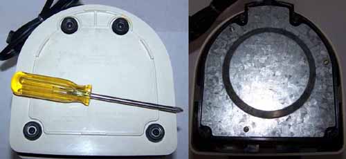 You will now see a sheet metal base that you can remove with your small Phillips screw driver(keep all of these screws in a safe place, so you don?t loose them): Inside the bakelite fan motor housing that you have just opened you will find three screw terminals with nuts and small lock washers. There are eight wires terminated at these terminals. There are two wires coming from the power cord, two wires from the fan motor, two wires from the heater circuit and two wires from the switch. The following two pictures show, first what it looks like physically with some colored arrows identifying which wires hook to which terminals and the second one is a very basic drawing (schematic) of the same information in a little more understandable form. The Yellow arrows identify the wires from the power cord; the Red arrows identify the heater wires (bare wires), the Blue arrows ? the fan circuit (red wires) and the green arrows ? the switch. P1 2-11 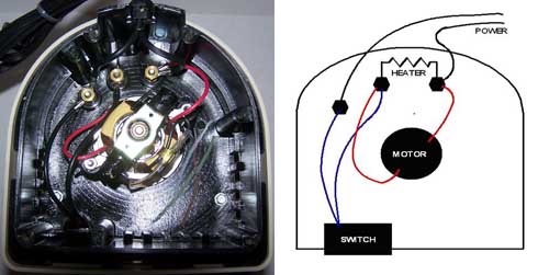 To follow this explanation of the wiring modification, orient your P1 the same as is shown in the picture (power cord enters the P1 on the opposite side from where you are viewing). There are two separate circuits within the P1 that receive power. Those circuits are the heater and fan circuits. As you can see a wire from each of these circuits is terminated at the screw terminal on the right and the other wire from each circuit it terminated at the middle terminal. The wires from the power cord go to the right terminal (with one wire each from the fan and heater) and the left terminal. The two wires from the switch go to the left terminal (with the single power wire attached) and to the middle terminal (with the other two heater and fan wires). So ? the way it works is: one wire from both the heater and the fan are hooked to one of the power wires, the second power wire has to get through the switch before getting to the other two heater and fan wires to power those circuits. What we are going to do is move one of the fan wires (the one on the middle terminal) to the left terminal along with one power cord wire and one switch wire. Everything else will be left as it is. BTW the nuts on the screw terminals require an 11/32" nut driver or socket. You should have a small pair or needle nosed pliers available to move the wires from and to the terminals - you may have to slightly bend the heater wire attached to the middle terminal, in order to remove the fan wire that we are moving. When tightening the nuts on the teminals - inspect all the wires to make sure they are not touching where they shouldn't. The following two pictures show the end product physically and in a schematic. The red arrow identifies the terminal to which we moved the fan wire (the only wiring change) P1 2-12 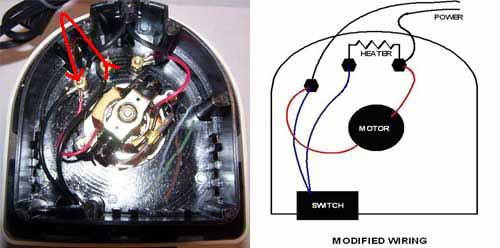 After replacing at least the metal bottom, plug the roaster in and test it. The fan should come on and stay on as long as the roaster is plugged in. When you switch the power switch to ?on? you should start feeling heat in the air stream within a few seconds. Turn the switch off and insure that the air cools down (it?ll take more time to cool than it did to heat up). If everything works as expected, you can replace the rest of the screws and the plastic bottom. You have finished this modification. Experiment with the heat switch while roasting to start lengthening portions of the roast ? such as the time between first and second crack ? by turning the heat off for 5 seconds and on for 10 seconds. By manipulating these times you can pretty much follow any profile you want to ? takes a little work but it will get you there. In a later article we will look at a way to automate this process. IF YOU?RE ROASTER WILL NOT REACH THE TEMPERATURES NECESSARY TO FINISH THE ROAST If you?re roaster falls into this category, never fear, there is an easy fix. It is going to take a little time but is easily accomplished. One third of the P1?s that I?ve dealt with have suffered this malady, the other two thirds work perfectly well without doing the ?thermostat? modification. I am aware of a couple of people whose roaster required this mod after roasting well for a year of more, the thermostats may become weak with continued use. The stock P1 includes a thermostat that limits the maximum temperature that it will reach. The next picture shows this thermostat as it looks when removed from the P1. P1 2-13 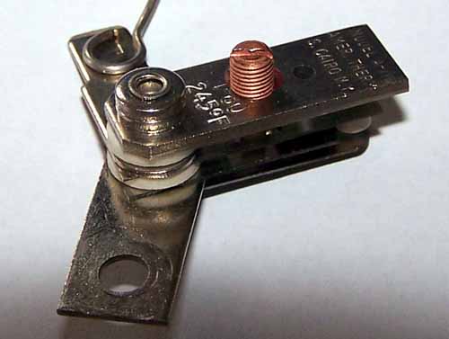 This next picture shows what happens when the bi-metallic element is heated ? it bends and allows the points through which the current to the heater must pass to open ? this interrupts the power to the heater, effectively turning it off. When the bi-metallic element cools sufficiently it will straighten back out and the points will close, turning the heater back on. This activity will keep cycling and maintain a rough approximation of the temperature at which the thermostat is set. P1 2-14  There are three ways of fixing the roaster if it will not reach the necessary temperature; the first is to reset the thermostat to a higher temperature. The second is to disable the thermostat. The third is to remove and/or wire around the thermostat. All of these methods require further disassembly of the P1. We have already covered removing the plastic and metal bottoms. We will need to remove all of the wires from the screw terminals and remove the wires leading to the switch and the switch from the outer plastic housing (manipulating the friction 'claws' on the switch with a screw driver while prying out on the switch will facilitate it's removal). P1 2-15  You can now turn the P1 right side up and remove the three Phillips screws holding the upper bakelite 'chute' base in place. With this piece removed the outer plastic housing will slide upward and off easily. Remove the two screws holding the bakelite chimney in place and remove the chimney. These last two screws require a ?? socket or alternatively, most screw drivers with removable bits are ?? internal hex. Removing the power cord now is just a matter of sliding it out of the base. The following pictures are of a P1 that has been completely disassembled to facilitate getting better quality pictures of the remaining disassembly. The two solid wires for the heater must be removed from the terminals and bent 'up' vertically as the P1 sets upside down on your work bench. The red arrows in this picture identify the location of three long screws that hold the bakelite base and the aluminum roasting chamber assembly together - their removal requires your ?? tool. After bending these two wires and removing the three screws you can carefully lift the base (including the fan assembly) off of the roast chamber assembly. P1 2-16 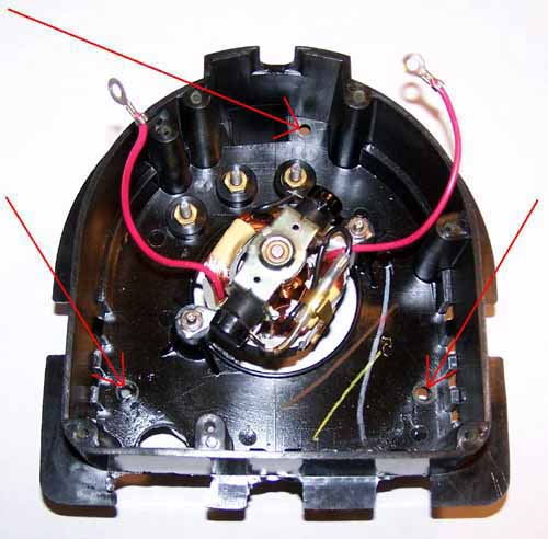 You will notice the small black bakelite piece in the upper part of the following picture - it is used to keep the heater wires from touching each other or the aluminum casting. Look this over carefully to make sure you will be able to reassemble the bakelite piece and the wires in the correct orientation to the casting and the bakelite base. P1 2-17 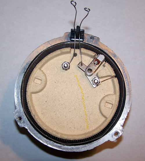 You may have noticed that several of the pictures show different thermostats, I have found three different makes of thermostats used in the P1. These are all functionally identical but slightly different in construction. The first method of fixing the thermostat problem is to reset the thermostat to a higher temperature. Without dis-assembling the roast chamber assembly further (don?t turn it upside down) you can remove the thermostat from the ceramic heater assembly by removing the 11/32? nut holding it. You may be able to loosen the brass adjusting screw shown in the following picture (the yellow arrow in the picture after that). If the thermostat in your P1 can be adjusted this way it will probably require holding the metal blade that the adjusting screw is threaded through with a pair of pliers and using a fair amount of effort on the screw driver. The screw is held in place, securely, with a thread locking material that must be broken loose. Backing the adjusting screw out (counter clockwise) two or three complete turns should reset the thermostat to a temperature above what is necessary for roasting. Re-seal the adjusting screw in place with red Lock Tite or JB Weld and reassemble the P1. P1 2-18 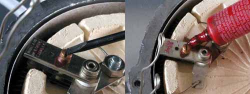 The second ?fix? to the thermostat problem is to permanently disable the thermostat. This will require removing the thermostat (one 11/32? nut) remove or destroy the small white nub identified by the red arrow in the following picture. When the bottom bi-metallic leaf bends upward it moves the upper of the two points by pushing up on this piece. If it is removed the points will stay in contact all the time. In one model of thermostat this piece is ceramic and can be crushed by your needle nose pliers, on another model of thermostat it will not crush and must be twisted out of the blade it is attached to or cut off with a small pair of side cutters. Make sure the points are firmly closed and neither blade with a point on it is touching the blades above or below when you are finished. If you have a multi-meter, checking continuity through the points may save another dis-assembly. P1 2-19 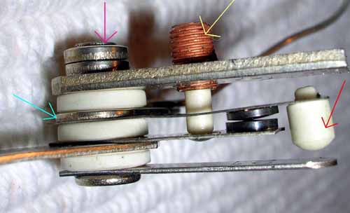 The third method of solving the thermostat problem is my personal favorite and is to just remove it. If you remove the thermostat (as above) and place the lower blade in a vise, you can grind or file the expanded metal from the top of the shaft (purple arrow) holding the assembly together. Loosen the vise a bit and using a punch (or nail) and hammer, pound the shaft out of the assembly ? be careful not to destroy the blade that the heater wire is attached (spot welded) to. When it is apart throw everything away except this blade, the one on the right side of the following picture. P1 2-20 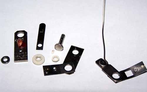 The thin blade with one of the points attached can now be broken off of the thick blade with the wire attached to it. P1 2-21 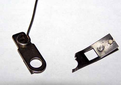 This blade can now be reattached, in place of the thermostat as you can see in the following picture. When you tighten the nut to hold it in place ? be sure the wire is oriented in the fashion shown, and re-bend it in the appropriate fashion to reach up through the base housing. This wire will be a little shorter than it was when attached to the thermostat, but will reach the screw terminal by judiciously bending it into place. P1 2-22 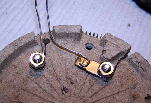 Re-Assembly You are now ready to re-assemble your roaster. Here is a quick check list of things to pay attention to ? in other words these have been easily forgotten things that caused problems for some folks doing these mods. If you removed the ceramic casting that the nichrome coil heating element and thermostat are mounted to: Remember to re-install the Mica insulation sheet in between the heater coils and the roaster housing: P1 2-23 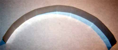 If this mica sheet were to break (it is very brittle), it is long enough to use a little red RTV High Temperature Gasket maker (identified in an earlier article) to attach the pieces together when overlapped. Be sure you let the RTV cure for a full 24 hours before using the roaster if you have to do this. This mica sheet MUST insulate the heater coil from the roast chamber casting or it will produce a direct short. P1 2-24  If you removed the entire heater unit ? remember to replace the aluminum plate (roast chamber floor) while reassembling. The hole you can see in the upper (11:00) portion of the picture is originally there to circulate hot air under the thermostat. Leave it as is or plug it with a small screw and nut. P1 2-25 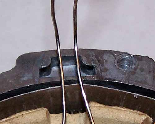 When the heater element is positioned correctly in the roast chamber casting the wires will line up with this small recess in the castings flange. P1 2-26 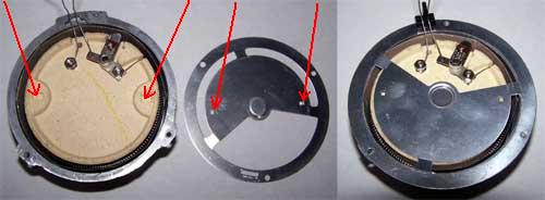 The aluminum seperator plate between the fan and the heater is positioned correctly by making sure the two small tabs in it are indexed into the corresponding recesses in the ceramic portion of the heater (red arrows in picture). The small bakelite wire guide / insulator (at 11:30 in the third picture) fits through the seperator plate and into the recess in the roast chamber casting flange. And the wires are bent to orient them correctly to allow the fan housing / base to be slide over them into place. The rest of the reassembly is pretty straight forward, the reverse of the dis-assembly. Mike B) Edited by NetriX on 04/24/2021 6:54 AM |
|
|
|
| Mike |
Posted on 02/19/2008 11:46 AM
|
|
1/2 Pounder Posts: 283 Joined: October 24, 2005 |
This is the third chapter in my presentation on Poppery 1 modifications. The following couple of pictures are of fully modified P1s. These machines use different switches, different model PID controllers and different ?type? thermocouples. They are however, along with a dozen or so others that I know of, work alike clones of each other. Fully modified P1s such as these are capable of roasting one half pound (net) roasts, back to back all day long. After reaching the end of roast, adjusting the fan to high speed will cool the roast to 250? F in a couple of minutes and is ready to roast again as quickly as you can unload the roasted beans into whatever you use for further cooling and reload it with greens. The roasting process (profile) itself can be infinitely modified and stored in the PID easily by interfacing the PID controller to a computer armed with some simple software. Very simple software is provided free with the controller and there is ?Coffee Specific? software in development (the Beta versions work great). The capabilities of this roaster depend on several key modifications. The first of these is enlarging the effective roast chamber size by adding a substantial chimney. The second necessary modification is variable speed fan control including the ability to ?push? the fan to 138 to 140 volts. And the third mod is controlling the heater section of the roaster with a programmable PID controller capable of a minimum of 4 ramp/soak segments (preferably twice that many). The ability to interface to a computer to facilitate PID programming requires it to be optioned with communication capabilities, otherwise the PID can be programmed from its front panel. The way I am going to write the remainder of this article is to: populate this thread with various pictures of the process, organize them to follow the three previously mentioned major modifications and finish by throwing the necessary verbosity in between the pictures. I'll be re-organizing and editing this post frequently and the more participation I get from readers the more interesting this process should be. This is obviously a fairly dramatic departure from the way articles are normally written - - we'll see how it works out. P1 3 0 1 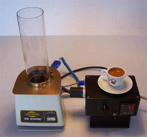 P1 3 0 2 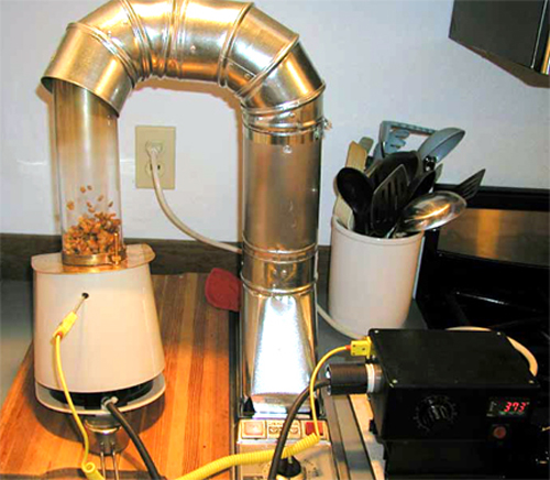 1 Bakelite Base Housing Increasing the air flow to allow a larger bean load while roasting in the P1 is one of our goals. To facilitate this, opening up the supply side for the fan is beneficial. In my testing, this modification by itself has increased the roasters green bean load by 25 gms in an otherwise completely modified P1. A variation, to accomplish the same result is to leave the sheet metal piece off of the bakelite base and perforate the bottom plastic piece (which the rubber feet attach to) and covering these perforations with a screen to disallow garbage being sucked into the roaster. I prefer the method shown in the pictures because it circumvents the problem of sucking garbage into the roaster and is considerably quieter. With the addition of a small amount of padding around the inside of the base of the outer plastic housing the noise of the fan can be further dampened. P1 3 1 1  P1 3 1 2  2 Outer Plastic Housing The measurement shown in this picture has been accurate for several roasters, but - - keep in mind that the outer plastic housing will be held in place by its interference with the horizontal flange (just below the air inlet holes) of the bakelite base housing. Differences in the original moulds for the base housing may require the outer housing to be cut to a different height. The accurate way of cutting the outer plastic housing is to fit it onto the base housing (roast chamber in place) with a small amount of downward pressure, being sure to center it. When everything is even, lay a pen or scribe across the top of the roast chamber opening and mark the inside of the plastic housing. Remove the housing, cut off and dispose of the upper portion of the housing. P1 3 2 1 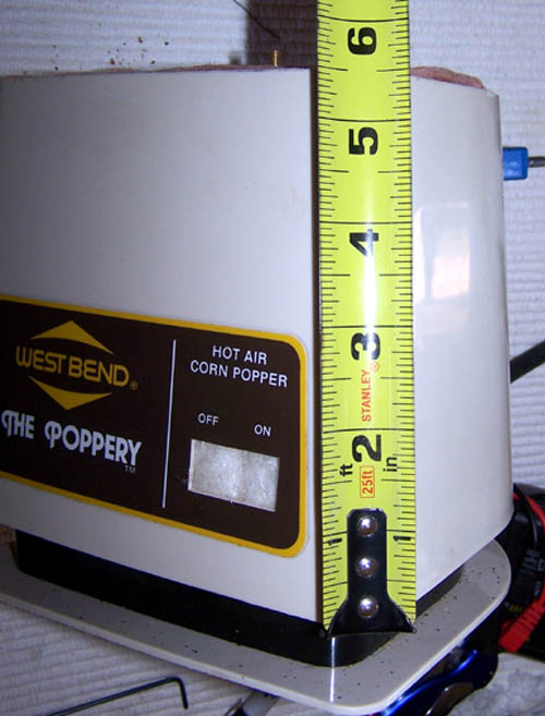 3 Top Plate P1 3 3 1  P1 3 3 2  P1 3 3 3  4 Chimney P1 3 4 1  5 Chimney Clamp P1 3 5 1 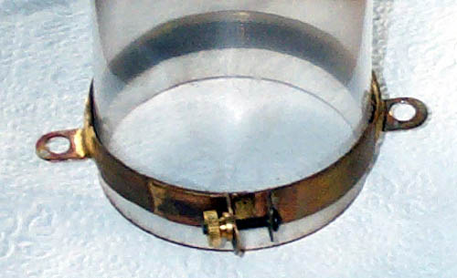 P1 3 5 2 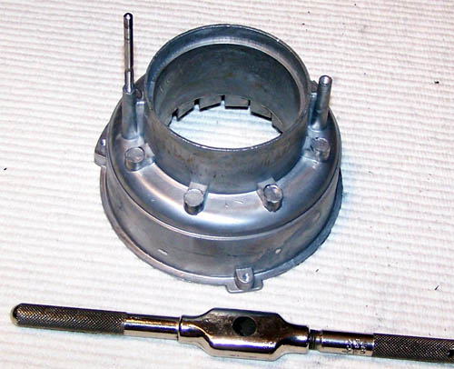 P1 3 5 3  P1 3 5 4  6 Dual and single power cords P1 3-x 7 Control Box P1 3 7 1 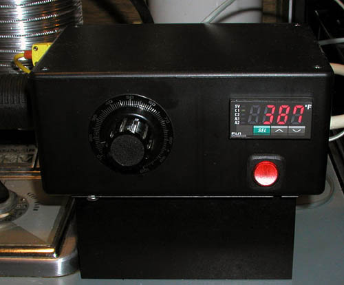 P1 3 7 2  I have recently acquired a Fuji PXG5 PID controller and built an enclosure for it. It is a DIN 8 size, so something larger than the standard Radio Shack box was required. The obvious add-on at the top of the box containing the row of togle switches, will be removed when I figure out which switches I want to permanently mount on the box. The PXG5 is set up with 5 digital inputs and these are temporary switches to manipulate the 5 optional controls. P1 3 7 3  8 Variable Speed Fan control P1 3 8 1 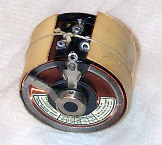 P1 3 8 2  9 Thermocouple placement P1 3 9 1  P1 3 9 2  10 TC cords and plug/receptacles P1 3-x 11 PID SELECTION It has taken me quite some time to figure out how to address the issue of PID selection. There are dozens of manufacturers that offer PID controllers and each one of them has several models, with many options. To the uninitiated, the selection of an appropriate controller can be an insurmountable roadblock to a roaster project. I am going to make some suggestions as to manufacturer, model and options......but first I'll try to explain in as much of a non-geek fashion as possible what a PID controller is. A PID controller used in a roaster is no more than a hot rodded thermostat. A simple thermostat will have a 'band' within which the temperature is controlled. A thermostat that is set for 100?F with a 10?F band will turn the heater on when the system cools to 95?F and turn the heater off when it reaches 105?F. A PID controller is designed to maintain the temperature with considerably less variation. Ideally, a PID controller would heat the system up to the target temperature of 100?F exactly and keep it there (no band). The acronym PID stands for the type of math that the micro-controller does to control the output. This miniature computer system does P (Proportional), I (Integral) and D (derivative) math on the values of current temperature, target temperature, rate of change of temperature, response of the controlled system to changes in the heat input etc. etc.........and a whole bunch of other things. If this type of thing trips your trigger, there is an overpowering amount of information on the math and how to implement it in different systems available with a simple google search. When roasting coffee we need to be able to change the rate at which the coffee is heated several times during the roast. A substantial portion of the PID controllers available today can be discounted immediately due to their inability to provide 'Ramp / Soak' abilities (or other descriptors meaning the same thing). This 'Ramp / Soak' ability of the remaining controller candidates allows us to do things such as heat up from 100?F to 200?F in 4 minutes (a 25?F per minute Ramp), Soak at that temperature for 0 minutes (no soak), and continue from 200?F to 300? in 5 minutes (a 20?F per minute Ramp). Most coffee roasting profiles can be accomplished with from four to six ramps. An example profile condensed to ramps is: Ambient temperature to 230?F - - - 2 minutes 230?F to 300?F - - - 2 minutes 300?F to 405?F - - - 4 minutes 405?F to 445?F - - - 6 minutes This roasting profile uses four ramps. When looking at PID controllers this is the minimum that will allow any flexibility in developing different roasting profiles. In many industrial applications a heat up Ramp is followed by a 'Soak' at the end prior to continuing the heat up with another ramp, this ramp / soak is described as two segments by many manufacturers. So, a controller capable of four ramps can be described as being capable of eight segments. Many of the current crop of PID controllers have 32 segment capability and the higher cost units may be able to store and switch between different ramp / soak profiles. The math being performed by the controller has a bunch of variables that allow it to be used in different types of systems. In older controllers, these variables are quantified by measuring temperatures and times as you heat up and maintain a given temperature in whatever system the controller is manipulating. The instruction book will walk you through the simple formulae used to produce these values. Newer controllers will have some type of automatic learning process that greatly simplifies the PID controller setup. Some of the newer controllers even have a 'fuzzy logic' feature that compensates for minor real time variations the controlled system may see. Another ability of some the most current PID controllers is measuring time in seconds rather than the traditional minimum time increments of minutes. I hope you understand that the above is a pretty basic description of these controllers. If you are shopping for a controller on EBay or other auction or surplus location, this description should give you some basic information to help identify a controller that may fit your needs. Due to the tremendous flexibility of PID controllers, there are frequently many dozens of optional configurations for any given controller. Before you buy anything, identify the manufacturer, the model no. and any other descriptors on the name tag that may be used to identify how it was optioned when originally purchased. Go to the manufacturer?s web site and download the manual for the controller. Read the manual and ensure that the controller is capable of accomplishing the required tasks. If you can't come up with a manual for the PID - don't buy it. PID controllers have from 30 to 200 individual parameters that may need to be turned off/on set or reset. Some controllers are optioned with RS 232 or RS 485 communication interfaces which allow manipulating and/or monitoring the controller via a computer or master controller, if you are planning on using this feature........make sure the software and whatever is necessary to 'talk' to the controller is available at a price you can live with (some companies provide free software - some companies want a second mortgage on your house for their software). PID controllers can normally be reprogrammed from the two or three buttons on the front face - changing a few parameters is fairly easy once you've accomplished it a few times. Checking, changing and experimenting with all of the settings from the front panel can be daunting, and impossible without a manual. BTW, when I say manual I don't mean just the sales brochure, the manuals for these things commonly go to a hundred pages or more. I hope the above has not scared you away from trying your hand with a low cost surplus controller that may cut the cost of your roaster project in half. I know a dozen folks who have built clones of my 'Ubber Popper' using PID controllers that cost less than 20% of what the Fuji model that I use. All of these folks are pretty technically proficient and several weren't successful until buying a second or third controller. When I built my first P1 based roaster, I used a variac to control heat. When I decided to use a PID controller with the P1 I had read everything I could by a plethora of folks who had used the Fuji controllers for espresso machine heat control and the half dozen or so people who had done similar roaster projects. I hesitate to name names in fear of forgetting someone. I am certainly not the first. Most people in the coffee community have defaulted to the Fuji PXR series of PID controllers. The reasons for this are probably pretty similar to mine, it is comfortable to have a community of folks who are familiar with the pitfalls of a complicated piece of equipment, and can help - - if problems arise. I am sure that all the major manufacturers produce a controller that is fully as capable as the Fuji. Omega, Watlow and many others are legend in the technology of temperature control and their equipment is undoubtedly fully capable. I have built a couple dozen clones of the 'Ubber Popper' and have used the Fuji PXR3 controller on all but four of them which use the Fuji PXR4. The only difference between the two (for our purposes) is that the '4' is a DIN 16 (48mm x 48mm) size with two lines of display, while the '3' is half height DIN 32 (48mm x 24mm) size with one line of display. The advantage to the '4' is that it displays the actual temperature on one line and the 'Set Value' (what the controller thinks the temperature should be at any given time) on the other line. With a '3' the two temperatures can be toggled to the display by pressing one of the three buttons on the bottom of the controllers face. OPTIONING THE CONTROLLER INPUT I have found that thermocouple input is the most cost effective - for me. The Fuji and many other recent generations of controllers can be reset to use different 'types' of thermocouples (J, K, T etc.). K thermocouples are the most appropriate and popular for roasting use, but if you already have another 'type' - - use it. Some PIDs have to be optioned for the specific input that you plan on using. Be sure to check this if you are planning on using a surplus PID. Some temperature input devices (even some types of thermocouples) can be prohibitively expensive. OUTPUT SSR (Solid State Relay) output is my normally used output. I'm currently testing an SCR (analog control) with high expectations. Many PIDs can be optioned with an 'onboard' relay capable of a 1 Amp or so current flow. This is obviously not enough to control a roaster heater of 1400 or 1500 Watts. If your PID has this as the output option, you can use it to trigger a larger (15 Amp or larger) relay or SSR. This 'onboard relay' is a mechanical relay and has a set of contactor points that will wear out considerably faster than the solid state device used with an SSR output option. Most PIDs can be optioned with one of several analog output signals such as 1 to 5 Volts DC, 1 to 10 Volts DC or 4 to 20 mA DC. This type of output signal can be used by a current carrying device such as an SCR controller to provide a variable voltage to the roasters heater rather than the off/on power that the SSR provides. An SCR type heater control scheme provides a smoothly variable heat output from the heater and may keep the system from seeing heat excursions such as is seen with the heater being either fully off or fully on when using an SSR or other relay control scheme. The disadvantage to SCR control is its cost. SCR devices capable of 15 Amps are available today in the $75 price range. An SSR of this size is in the $25 range. The heat excursion tendency of the SSR control scheme can be minimized by setting the off/on cycle time (period) to a short time such as one half second. There has been debate about these two control schemes and I would recommend that you research it and make your own decision. RAMP / SOAK As I have mentioned previously, a controller that allows at least four ramps is necessary - more is better. AUTO TUNE A controller with the auto tune feature greatly simplifies set up initially. This feature is also useful to re-tune your roaster to compensate for things like a change in inlet air temperature from summer to winter if you roast in a location without a fairly consistent ambient temperature. Substantial changes to your roasters green bean load or other changes to the roaster systems environment can be quickly and easily compensated for with the auto tune feature. FUZZY LOGIC Many of the last couple of generations of PIDs have a 'fuzzy logic' feature that allows the PID to do minor compensations to control setup in real time during operations. I have had good luck using this feature; some other folks believe they do better with the fuzzy logic feature turned off. COMMUNICATIONS RS 485 is a communications protocol that is widely used in industrial environments to communicate between various types of controllers such as computers and devices such as PIDs. It is similar to the RS 232 serial communications found on most home PCs and inexpensive converters can be purchased which allow a computer with a serial (or even USB ) to talk with an RS 485 communications system. RS 485 communications is a two way protocol (the PC and the controller can talk to each other). Another communications protocol that is becoming popular in the newest PIDs is the 'loader' port. The loader port is usually an RS 232 port on the controller (frequently a small stereo head set type connector) that allows loading the complete parameter set into the PID. Some specific units include the ability of the controller talking to the computer in real time in the same manner as RS 485. Being able to communicate with your PID from your PC allows easy setup, roast monitoring including data logging individual roasts and even complete computer control of the roaster system in some circumstances. I recently made a fairly significant change to my base (most commonly used) roasting profile and needed to proliferate this change to the couple dozen clones of my roaster that people are using. All of the roasters that I build use PIDs with the RS 485 communications option, so it was relatively easy to email the new profile to the folks involved and talk the less technically inclined among them through the process of updating their PIDs. Marc Cohen has produced a roaster specific software program that takes this one step further. His program is specific for the Fuji PXR series of PIDs with RS 485 communications option. The program allows real time PC interface and control of these PIDs and includes the ability to change profiles and use specific profiles for specific beans, green bean stash management, graphing and logging roasts and many other coffee geek types of functions. OTHER OPTIONS The only other PID options that I regularly use are the DI (digital input) and DO/ALARM (digital output) functions. The DI is the ability of the PID to see whether two terminals are shorted of not, so if you hook a toggle switch to these two terminals the PID can be programmed to perform a variety of operations depending on the position of the toggle switch. I use this to start of stop the ramp / soak profile. Other uses for the digital inputs are operations such as resetting alarm states, standby off/on and various other operations that are specific to different PIDs. I have been experimenting with a DO (digital output) signal to switch a resistor into my roasters fan circuit to manipulate fan speed during the roast. PIDs can commonly be optioned with several DIs and DOs. SPECIFIC RECOMMENDATIONS As you have already figured out from the above description, there are a lot of PID controllers that will function well in a coffee roaster. Making specific recommendations among the field of available controllers would take considerably more experience with the various makes and models than I have. I can, however, recommend the controllers that I use; the Fuji models PXR3 and PXR4. As I have indicated above, the only advantage to the PXR4 over the PXR3 is that the former has a two line display allowing it to indicate the set temperature and the actual temperature at the same time, this increased indication costs $40. The options that I include when ordering a PID are: Input - Thermocouple, Farenheit indication Output #1 - SSR (Solid State Relay) Output #2 - None Alarms - None Power Supply - Standard (100 - 240 Volt, 50/60Hz) Additional Functions - RS485 Communications and a single Digital Input (DI) The model # for a PXR3 with these options is: PXR3-RCY1-4VVA1 The model # for a PXR4 with these options is: PXR4-RCY1-4VVA1 I purchase my controllers from TTI Global, their phone #'s are 802-863-0085 and 800-884-4967 and web site is http://www.ttiglobal.com . The gentlemen that I order from if doing so on the phone are Dwight or Shawn (I'm sure there are other folks there that are capable of dealing with orders). You can get the PXR setup with my profile by requesting it to be programmed with "ubber popper.pxr", I believe they keep a copy of Jim Schuleman's program also. Fuji has recently come out with a new series of PID controllers, dubbed the "PXG" series. The PXG controllers have all the advantages of the PXRs with the advantage of being able to reset the time increments to minutes and seconds rather than the minimum time increments of hours and minutes of the PXR series. The PXG also has a built in RS 232 "loader" port, which will allow easy loading of new profiles to the controller, and so far it seems to provide the two way communications needed for computer monitoring and/or real time control during the roast. I recently purchased a PXG5 controller with a firly broad range of options which I plan on thoroughly testing in a roaster, so I may have new information on this in the near future. Mike B) Edited by Mike on 02/19/2008 11:49 AM |
|
|
|
| paul_helbert |
Posted on 02/19/2008 9:18 PM
|
|
Newbie  Posts: 1 Joined: January 23, 2008 |
Mike, Thanks for the article on the PID P1. I don't know how I came to find it on the day it was posted or how I should keep up with the discussion of it. I'm a trailing edge technology guy so, I'll be trailing along probably will the PID mod within the year. Thanks, Paul Helbert Tenth Legion, VA |
|
|
|
| Mike |
Posted on 02/20/2008 11:45 AM
|
|
1/2 Pounder Posts: 283 Joined: October 24, 2005 |
Paul, The above has been listed as three different threads untill yesterday. Any help that I can give ... don't hesitate to send me a PM. Mike B) |
|
|
|
| seedlings |
Posted on 02/20/2008 5:41 PM
|
 1 1/2 Pounder  Posts: 4226 Joined: June 27, 2007 |
Mike, this article is why I joined homeroasters. A+ CHAD Roaster: CoffeeAir II 2# DIY air roaster
Grinder: Vintage Grindmaster 500 Brewers: Vintage Cory DCU DCL, Aeropress, Press, Osaka Titanium pourover |
|
|
|
| Island Addict |
Posted on 08/13/2008 9:42 PM
|
|
1/4 Pounder  Posts: 55 Joined: August 13, 2008 |
I want to thank you for this detailed and extremely useful post. I've been a coffee geek for a while, but am just now getting into roasting. I snagged a Poppery I on eBay and can't wait to get my hands on it and start roasting and modding. Rob |
|
|
|
| Island Addict |
Posted on 08/16/2008 9:57 PM
|
|
1/4 Pounder Posts: 55 Joined: August 13, 2008 |
Quote Marc Cohen has produced a roaster specific software program that takes this one step further. His program is specific for the Fuji PXR series of PIDs with RS 485 communications option. The program allows real time PC interface and control of these PIDs and includes the ability to change profiles and use specific profiles for specific beans, green bean stash management, graphing and logging roasts and many other coffee geek types of functions. Where can I find this software or something similar? I'd really like something that will do real time graphing of data from two thermocouples (environment and bean) and save the data in CSV format. |
|
|
|
| Dan |
Posted on 08/17/2008 7:06 AM
|
|
1 1/2 Pounder Posts: 1662 Joined: October 24, 2005 |
Check with the mfgr., in this case Fuji. Or, try Omega. |
|
|
|
| Island Addict |
Posted on 08/17/2008 10:31 AM
|
|
1/4 Pounder Posts: 55 Joined: August 13, 2008 |
The trouble is I am the manufacturer, making my own thermocouple hardware. I'm hoping someone has already written an open source, roasting-specific application. If not, I'm going to dust off my coding skills. |
|
|
|
| jlyon10 |
Posted on 06/22/2009 1:29 PM
|
 1/4 Pounder Posts: 101 Joined: April 01, 2009 |
I got the Popper I at the coffee kids auction and I made the 1st modification with the tin can and roasted with it this week-end. It works really great. One question I do have. I roasted by sight and sound. I got what I was looking for but it seems like the volume is not the same as when I roast the same beans in a Fresh Roast Plus 8. Any Ideas why?
Jim Lyon
Jim's Coffee Beans |
|
|
|
| seedlings |
Posted on 06/24/2009 10:56 AM
|
|
1 1/2 Pounder Posts: 4226 Joined: June 27, 2007 |
Glad to hear the P1 is doing what it's made to do! More or less volume than you expected? CHAD Roaster: CoffeeAir II 2# DIY air roaster
Grinder: Vintage Grindmaster 500 Brewers: Vintage Cory DCU DCL, Aeropress, Press, Osaka Titanium pourover |
|
|
|
| jlyon10 |
Posted on 06/25/2009 1:50 PM
|
|
1/4 Pounder Posts: 101 Joined: April 01, 2009 |
Less, I think it is an awsome machine
Jim Lyon
Jim's Coffee Beans |
|
|
|
| seedlings |
Posted on 06/26/2009 8:54 PM
|
|
1 1/2 Pounder Posts: 4226 Joined: June 27, 2007 |
Have you tried setting it on, say, a 30 degree angle? May get a few more greens in there. CHAD Roaster: CoffeeAir II 2# DIY air roaster
Grinder: Vintage Grindmaster 500 Brewers: Vintage Cory DCU DCL, Aeropress, Press, Osaka Titanium pourover |
|
|
|
| jlyon10 |
Posted on 06/29/2009 8:12 AM
|
|
1/4 Pounder Posts: 101 Joined: April 01, 2009 |
I was playing with it Saturday and held it tipped by hand.
Jim Lyon
Jim's Coffee Beans |
|
|
|
| jlyon10 |
Posted on 09/01/2009 7:59 AM
|
|
1/4 Pounder Posts: 101 Joined: April 01, 2009 |
I'm sure everyone knows this already but my Fresh Roast Plus 8 chaff collector top fits on the soup can on the poppery. Will I have problems with it melting or something while using this chaff collector on the soup can?
Jim Lyon
Jim's Coffee Beans |
|
|
|
| John Despres |
Posted on 09/02/2009 11:30 AM
|
 Administrator Posts: 2221 Joined: January 09, 2008 |
Jim, I'm sure there will be no problem at all. The temperatures are close between the two roasters and the venting should be fine. John Respect the bean.
John Despres Fresh Roast 8, Gene Cafe, JYTT 1k, Quest M3, Mazzer Mini, Technivorm, various size presses and many more brewers. |
|
|
|
| jfrescki |
Posted on 10/26/2009 8:53 AM
|
|
Newbie Posts: 4 Joined: October 24, 2009 |
Mike, can't thank you enough for this info. I was really frustrated with the thermostat screwing up my roasts on the poppery1. I was about to give up on it when I found this. I had the fan motor and thermostat mods done within 15 minutes of reading this, and it can't work better now. |
|
|
|
| jbhoren |
Posted on 02/04/2010 3:39 PM
|
|
Newbie Posts: 2 Joined: April 16, 2009 |
Quote jlyon10 wrote: I'm sure everyone knows this already but my Fresh Roast Plus 8 chaff collector top fits on the soup can on the poppery. Will I have problems with it melting or something while using this chaff collector on the soup can? I recently read your post and, with Great Expectations, ordered a Fresh Roast +8 chaff collector, hoping to "mate" it with a clear Pyrex tube that I'd friction-fitted into the roasting chamber of my Poppery I. It was not to be. Both units have the same inner/outer diameters, and the chaff collecter will neither fit into, nor around, the Pyrex tube. Has anyone run into this; and, if so, how did you solve the problem? i.e., a solution for mating the two securely (such as a metal or plastic collar), but without placing a too-great mechanical stress on either part (especially the glass) or impeding the flow of chaff. It's impossible to roast outside, when the temperature's -30*F, and while I'm willing to open the door to ventilate any smoke, the chaff's a killer! Edited by jbhoren on 02/04/2010 3:59 PM |
|
|
|
| seedlings |
Posted on 02/05/2010 7:44 AM
|
|
1 1/2 Pounder Posts: 4226 Joined: June 27, 2007 |
If you're doing the "traditional" charge of about 1/2 cup of beans, use the original hood on the poppery to direct the chaff into a bowl, or the sink. It always worked well for me. If you're doing a larger load requiring a chimney, then I've seen guys get some flexible aluminum duct (and maybe a duct blower fan) to vent outside. No smoke, no chaff. Well, actually the birds love chaff... CHAD Roaster: CoffeeAir II 2# DIY air roaster
Grinder: Vintage Grindmaster 500 Brewers: Vintage Cory DCU DCL, Aeropress, Press, Osaka Titanium pourover |
|
|
|
| milknmycoffee |
Posted on 02/05/2010 6:39 PM
|
|
1/4 Pounder Posts: 143 Joined: December 26, 2009 |
Thanks for posting this wonderful posting. My husband modified my Poppery I, splitting the fan and heat switch as well as changing the thermostat. He said your instructions were excellent...and he is a complete tech head (former Apple software engineer). |
|
|
|
| DavidG |
Posted on 02/07/2010 12:11 AM
|
 1/2 Pounder Posts: 218 Joined: April 20, 2009 |
An interim solution while I save up for a PID controller... After separating the heater and the fan circuits completely, I added a power cord so that I can independently power each (lots of other posts detail how to do this). Then, I plugged the heater power into a router speed controller (at Seedlings suggestion) that I picked up at Harbor Freight for $20. With practice this is a huge improvement over manually switching on/off in rapid succession. David europiccola | yama + coryrod | chemex | AP | clever
wbp1 | wepp1 | bm/hg | co hybrid (still coming soon...) |
|
|
|
| bikerbob |
Posted on 09/26/2010 9:36 AM
|
|
Newbie Posts: 5 Joined: September 21, 2010 |
I am attempting to mod and air popper. The popper I hav differs from the one in the article. I have include a sketch of my wiring; the dashed line is my propsed wiring to by bypass the thermal fuse. Can you confirm if this is correct or supply the correct wiring thanks bikerbob
bikerbob attached the following file:
|
|
|
|
| j_allen |
Posted on 02/04/2011 10:46 AM
|
|
Newbie Posts: 3 Joined: February 03, 2011 |
Just finished my first mod. of the PI; increased the size of the roasting chamber, removed the thermostat and rewired the fan. http://forum.home...ad_id=2115 Jim *edit: added link to new thread -CHAD Edited by seedlings on 02/04/2011 11:13 AM |
|
|
|
| j_allen |
Posted on 02/11/2011 10:30 PM
|
|
Newbie Posts: 3 Joined: February 03, 2011 |
Newbie here, i'm a Chef not an engineer. I built a control panel for the Poppery II according to Felix Dial; works fine. Now that i have a Poppery I, can I run the fan booster through the same transformer/dimmer setup, or will there be a problem? http://members.co...oast.shtml PI = 1500W .84amp. PII= 1400W .95amp Fan control setup= 600W dimmer & 25.2V CT 2.0A heavy duty transformer. Both machines have had heat and fan circuit split and thermostat disabled. I'll be upgrading to a PID as soon as the boss approves. If anyone has a spare Variac lying around, I would be interested! Had to start roasting, our local independent roaster started charging $17.00lb. I guess you have to pay for the Probat and Probatino!!
j_allen attached the following image:

|
|
|
|
| pgyouth |
Posted on 02/21/2012 10:48 PM
|
|
Newbie Posts: 1 Joined: February 21, 2012 |
Great post!
|
|
|
|

| Jump to Forum: |
Powered by PHP-Fusion Copyright © 2024 PHP-Fusion Inc
Released as free software without warranties under GNU Affero GPL v3
Designed with ♥ by NetriXHosted by skpacman