
Login

Shoutbox
You must login to post a message.
renatoa
07/26/2024 3:49 PM
Bill grubbe and Jk, 
allenb
07/26/2024 5:15 AM
Spiderkw Welcome to HRO!

renatoa
07/24/2024 8:31 AM
ramiroflores and John123,

 ?
?
?renatoa
07/21/2024 1:18 AM
 , Luislobo
renatoa
07/19/2024 11:28 AM
Koepea,
Forum Threads
Newest Threads
Skywalker roaster modsBackground Roast Iss...
Hello from Arkansas
TC4ESP
Green coffee reviews
Hottest Threads
| Skywalker roaster... | [375] |
| TC4ESP | [115] |
| War on Farmers by... | [47] |
| Adventures in flu... | [26] |
| Hello! (soon) Roa... | [17] |
In Memory Of Ginny

Donations
Latest Donations
dmccallum - 10.00
JackH - 25.00
snwcmpr - 10.00
Anonymous - 2.00
Anonymous - 5.00
dmccallum - 10.00
JackH - 25.00
snwcmpr - 10.00
Anonymous - 2.00
Anonymous - 5.00
Users Online
Guests Online: 3
Members Online: 0
Total Members: 8,393
Newest Member: Bill grubbe
Members Online: 0
Total Members: 8,393
Newest Member: Bill grubbe
View Thread
Who is here? 1 guest(s)
 Roastlogger and Artisan Arduino code
|
|
| alexcampbell |
Posted on 12/30/2013 1:03 PM
|
|
Newbie  Posts: 42 Joined: December 16, 2013 |
Hello, This is my first coffee roasting post in any forum. I have started roasting quite recently, but I am fairly experienced with embedded electronics projects. I currently have a Poppery I with a great PID controller that was originally designed for controlling reflow ovens for soldering SMT components. It allows you to import a .CSV profile with unlimited stages of RAMP, Soak etc. It is called a TECHFX reflow controller by Silicon Horizon that is now, unfortunately out of business. I am gathering parts and controls to build a much larger fluid bed roaster. I am looking for information on the serial communications that happens between the Roastlogger and Artisan programs and the Arduino. I have found the code that needs to be sent to roast logger for temperature, but I need the control information sent back as heat control. I have the code for both, but instead of cleaning up those scripts, I want to build my own Arduino code to run my roaster. I love the functionality of the programs and I want to try with an arduino. Unfortunately, with no TC4s available, I will have to build my own input and output circuitry, but that should be the easy part. I plan on using an SSR to do away with the zero crossing and I am going to use strictly the computer interface, so I do not need the LCD interface code. Any help would be appreciated. Also, just to clarify, on Artisan, the alarms are the only way of inputting a profile and there is no "real" PID functionality? Thank in advance. Edited by alexcampbell on 12/30/2013 1:12 PM |
|
|
|
| ginny |
Posted on 12/30/2013 1:51 PM
|
 Founder Posts: 3476 Joined: October 24, 2005 |
Quote I have the code for both what is your issue if you have the codes for both? ginny |
|
|
|
| snwcmpr |
Posted on 12/30/2013 4:16 PM
|
 1 1/2 Pounder  Posts: 925 Joined: March 03, 2011 |
Have you seen the DIY section here on this forum? Ken --------------
Backwoods Roaster "I wish I could taste as well as I wish I could roast." As Abraham Lincoln said "Do not trust everything you read on the internet". |
|
|
|
| JackH |
Posted on 12/30/2013 4:41 PM
|
 Administrator Posts: 1809 Joined: May 10, 2011 |
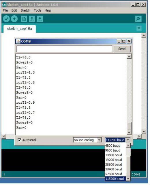
Hello Alex and welcome to Homeroasters! The RoastLogger TC4 sketch sends continuous serial data at 115,200 baud. I have attached a screenshot of the Arduino IDE serial monitor. It is simple text with a newline: T2=76.0 Power%=0 Fan=0 rorT2=1.0 etc... The same data over and over with changing values. For the Artisan TC4 sketch: The Artisan software sends a request and the TC4 sends a packet of information at 19,200 baud. The following is a list of commands for Artisan/TC4 Serial Commands for aArtisan ============================ Notes: 1. Terminate all command strings with newline, i.e. /n 2. Delimiters between parameters may be comma, space, semicolon 3. First four characters (max) of command name are significant CHAN,ijkl ----------- where i,j,k,l = a decimal value 0 to 4 representing a physical port Establishes the active logical channels (chan1, chan2, chan3, chan4) and maps them to physical ports (TC1, TC2, TC3, TC4). A value of zero for the physical port inactivates the channel. Response from TC4 device is "# Active channels set to ijkl" Examples: chan,1200/n TC1 -> chan1, TC2 -> chan2, chan3 and chan4 inactive chan,3210/n TC3 -> chan1, TC2 -> chan2, TC1 -> chan3, chan4 inactive UNITS,u --------- where u = C or F. Sets active temperature scale. No response from TC4 device. READ ------ Requests current temperature readings on all active channels. Response from TC4 device is ambient temperature followed by a comma separated list of temperatures in current active units in logical channel order: ambient,chan1,chan2,chan3,chan4 OT1,duty ------- where duty = 0 to 100 (percent output) Changes the PWM duty cycle on OT1 to p. No response from TC4 device. OT2,duty ------- where duty = 0 to 100 (percent output) Changes the PWM duty cycle on OT2 to p. No response from TC4 device. IO3,duty ------- where duty = 0 to 100 (percent output) Changes the PWM duty cycle on IO3 to p. No response from TC4 device. DWRITE,pin,val ---------------- where pin = Arduino pin number (D0 to D13 or A0 to A5) val = HIGH or LOW Puts port associated with pin number in output mode and sets it HIGH or LOW. No response from the TC4 device. AWRITE,pin,level ------------------ where pin = Arduino pin number (D0 to D13) val = 0 to 255 Puts port associated with pin number in output mode and sets output level 0 to 255 (i.e. duty cycle 0 to 100%). No response from the TC4 device. I hope this helps.
JackH attached the following images:

Edited by JackH on 12/30/2013 5:04 PM |
|
|
|
| alexcampbell |
Posted on 12/30/2013 5:07 PM
|
|
Newbie Posts: 42 Joined: December 16, 2013 |
Thank you, That is exactly what I was looking for. As for why I was looking for the information if I had the code? The code for the TC4 uses analog values, has code for an LCD screen etc. I want to write a new sketch that uses an SPI interface thermocouple amplifier and has a simple SSR output. This would allow you to run an arduino without a shield as a roast controller. If I write a clean script, anyone should be able to interface a standard arduino with RoastLogger |
|
|
|
| JackH |
Posted on 12/30/2013 5:18 PM
|
|
Administrator Posts: 1809 Joined: May 10, 2011 |
Glad to help. Why not build your own TC4 shield? We have a source to order the PC fabs. The V4.0 shield is open source. http://forum.home...ad_id=3548 |
|
|
|
| alexcampbell |
Posted on 12/30/2013 10:09 PM
|
|
Newbie Posts: 42 Joined: December 16, 2013 |
The main reason that I do not want to build the TC4 Shield is because I already have an Arduino and thermocouple breakout. I have transistors and solid state relays as well from past projects. I am not a huge fan of LCD displays for monitoring or programming so I don't need that either. |
|
|
|
| Barrie |
Posted on 12/30/2013 11:42 PM
|
|
Pounder  Posts: 504 Joined: April 10, 2012 |
Jack, I have been 'reading the mail' here and in the TC4 DIY project (terrific job), and notice in this thread the big difference in transfer rates that you quote for both RoastLogger and Artisan. As you know, I have converted to Artisan now, but was impressed by the informative and stable RoR info when I was using RL. To me it is still the one problem area with Artisan, with a constant conflict between accuracy and smoothness. Marko has provided a nice explanation over on the HB forum, but now I am wondering to what extent the transfer rate difference is a factor? Any thoughts on this? Barrie. Barrie (San Diego, CA)
"So much to learn, so little time." Hottop 2K+., Artisan, Jura Capresso ENA 3 (i.e. espresso). |
|
|
|
| MaKoMo |
Posted on 12/31/2013 3:56 AM
|
|
1/4 Pounder  Posts: 127 Joined: April 06, 2011 |
You can easily change the serial speed in the aArtisan sketch to that of the RoastLogger sketch and change the serial port settings in Artisan accordingly. I did that and this does not influence the RoR issue in any way. However, it let's the Artisan software waiting less for the readings coming from the TC4. |
|
|
|
| JackH |
Posted on 12/31/2013 3:58 AM
|
|
Administrator Posts: 1809 Joined: May 10, 2011 |
Hi Barrie, The TC4 RoastLogger sketch calculates and transmits RoR for both T1 and T2 temperatures. If you look at the aArtisan TC4 commands, you will not find any RoR read. I think that the Artisan application does it's own RoR calculations where the RoastLogger application just uses the RoR values transmitted from the RoastLogger TC4 sketch. I don't know if the data rate matters too much. RoastLogger grabs the data when it can, the TC4 is sending it constantly. Artisan sends a read request to the TC4 and waits for the data. I really like the display and function of Artisan, but I find the RoR to be unstable for me. I have even tried the Celeron version of Artisan with similar results. This is just logging/monitoring with no other actions. I am getting RoR readings swinging from 80 then 33 then 80, etc. Maybe the software could be written to filter out these large numbers. To be fair, I am not using the fastest laptop. But I have tried stripping all unneeded Windows services and all it runs is roasting software. These are just my observations. I could be missing something. Edited by JackH on 12/31/2013 5:41 AM |
|
|
|
| MaKoMo |
Posted on 12/31/2013 7:21 AM
|
|
1/4 Pounder Posts: 127 Joined: April 06, 2011 |
So in the RoastLogger case, the meter (ie. the TC4) is doing the "better" smoothing also on the RoR. That makes sense, but Artisan is used with a lot other devices that do not submit RoR values. So this is not an option. However, smoothing as early as possible, using "slow" probes (in contrast the often here and in other places suggested "fast" probes) is the best you can do. I wrote about the general issue here http://www.home-b...ml#p327239 In case of the TC4/aArtisan, you can influence the smoothing done on the temperature values in the user.h. I increased the smoothing values from 10 to 20 as follows Code Download source #define BAUD 115200 // serial baud rate Smoothing the temperature values more, also smoothes the RoR values calculated by Artisan. Just change the values in the user.h and upload the firmware to your TC4 to check the effects. You see from the RoastLogger sketch Code Download source #define RISE_FILTER 85 // heavy filtering on non-displayed BT for RoR calculations that the RoR is calculated on a heavily filtered BT and is itself heavily filtered itself. If done in the meter/TC4, the resulting time lag is smaller as the sampling rate is way higher than the values that finally find their way to the connected app. |
|
|
|
| JackH |
Posted on 12/31/2013 3:00 PM
|
|
Administrator Posts: 1809 Joined: May 10, 2011 |
Thanks for the reply Marko. I understand about having to support multiple devices. I will try those settings and see if the RoR settles down. The temperatures do seem steady. My probes are fairly fast. |
|
|
|
| alexcampbell |
Posted on 01/04/2014 12:39 PM
|
|
Newbie Posts: 42 Joined: December 16, 2013 |
So I have been sorting through code for a couple of days now and I am having a couple of small issues. I have been able to manipulate the data coming from the Arduino to the RL software using the MAX6675 sketch. However, when I try to write a simple, standalone sketch to send data back to RL, It does not work. My goal is to use only the computer control mode of RL for my roaster, so I have been trying to clean out all of the "controlby arduino" and PID code to have a barebones sketch that reads the power level coming back from the PC and sends back the temps to RL. In Computer mode, does the sketch load the values for PID into the Arduino, or does it simply send the power level to the Arduino? Any help? I am guessing that someone has done this before. Edited by alexcampbell on 01/04/2014 12:48 PM |
|
|
|
| JackH |
Posted on 01/04/2014 7:23 PM
|
|
Administrator Posts: 1809 Joined: May 10, 2011 |
Alex, There may be some members here that have used the MAX6675 sketch. You could also contact Tom Coxon who wrote RoastLogger for more information about the sketch. |
|
|
|
| alexcampbell |
Posted on 01/05/2014 2:03 AM
|
|
Newbie Posts: 42 Joined: December 16, 2013 |
Thanks Jack. The issue with the Max6675 Sketch is that it doesn't seem to allow computer control of the Arduino. As far as I can tell, the code is not there to take the power serial data and convert it into a PWM for the output. I appreciate the assistance. |
|
|
|
| JackH |
Posted on 01/05/2014 8:05 AM
|
|
Administrator Posts: 1809 Joined: May 10, 2011 |
I took a look at that sketch and the PID library. I guess the PID library is beta. Maybe there is some other hardware needed for the PWM (transistor drivers for a SSR, etc). It seems like it would be a shield for the Arduino. It seems to imply that additional hardware is needed. Either a TC4 or HTC board or one of your own design. |
|
|
|
| MaKoMo |
Posted on 01/05/2014 11:09 AM
|
|
1/4 Pounder Posts: 127 Joined: April 06, 2011 |
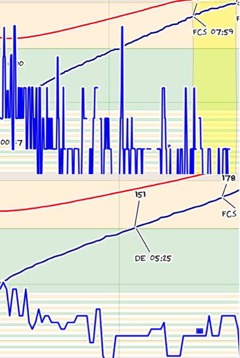
Quote MaKoMo wrote: Smoothing the temperature values more, also smoothes the RoR values calculated by Artisan. Just change the values in the user.h and upload the firmware to your TC4 to check the effects. In the attached file you see the effect of moving from the default Code Download source BT_FILTER 10 in user.h to Code Download source BT_FILTER 50 The effect is most visible on the BT RoR. This was just a test and I will move further to 80 in my setup and will never buy unshielded probes for roasting again. The ones in my Hottop used for this recoding are the Omega XCIB-K353 and you can see each bean bumping against the probe in the BT curve. For the ET those probes might be fine. Marko
MaKoMo attached the following image:
|
|
|
|
| alexcampbell |
Posted on 01/06/2014 2:19 PM
|
|
Newbie Posts: 42 Joined: December 16, 2013 |
I think I have been able to strip out the control commands from the TC4 sketch. The Roastlogger software sends commands to the Arduino if it is set to computer control. That is what the PID settings are for in the Arduino interface portion Roastlogger. It sends out information that will tell the Arduino that it is in PC control mode, followed by power and fan settings. The arduino feeds back the temperature and power settings to RL. I do not want to build a standalone unit, so all I want is to translate the signals from the PC into control signals for the Arduino that will drive SSRs for my heater and fan. The arduino will more or less be a serial interface as opposed to a controller that sends back data logging signals. I think that there is a lot of people that would be quite happy with a simple system like this. |
|
|
|
| alexcampbell |
Posted on 01/08/2014 11:14 AM
|
|
Newbie Posts: 42 Joined: December 16, 2013 |
I have now had success. I took the MAX31855 RL sketch and made a bunch of modifications to it. -I added in full PWM fan control -I changed the 0-100% incoming power setting to a 0-255 PWM signal for my heater SSR -I have stripped out the PID control and arduino control settings and variables to be able to run in computer control mode only. -I have added in code that can be commented out that uses a potentiometer for simulation and debugging. To Do: -I have ordered an I2C display that I may incorporate onto the roaster for manual control runs. The way that I will implement manual control is similar to the Hottop in that if both pots are at Zero, it will wait for computer input, if both are off zero, it will run in standalone manual mode. - I need to add in failsafe code that will not allow heat if the fan is off. |
|
|
|

| Jump to Forum: |
Powered by PHP-Fusion Copyright © 2024 PHP-Fusion Inc
Released as free software without warranties under GNU Affero GPL v3
Designed with ♥ by NetriXHosted by skpacman