
Login

Shoutbox
You must login to post a message.
renatoa
07/26/2024 3:49 PM
Bill grubbe and Jk, 
allenb
07/26/2024 5:15 AM
Spiderkw Welcome to HRO!

renatoa
07/24/2024 8:31 AM
ramiroflores and John123,

 ?
?
?renatoa
07/21/2024 1:18 AM
 , Luislobo
renatoa
07/19/2024 11:28 AM
Koepea,
Forum Threads
Newest Threads
Skywalker roaster modsBackground Roast Iss...
Hello from Arkansas
TC4ESP
Green coffee reviews
Hottest Threads
| Skywalker roaster... | [376] |
| TC4ESP | [115] |
| War on Farmers by... | [47] |
| Adventures in flu... | [26] |
| Hello! (soon) Roa... | [17] |
In Memory Of Ginny

Donations
Latest Donations
dmccallum - 10.00
JackH - 25.00
snwcmpr - 10.00
Anonymous - 2.00
Anonymous - 5.00
dmccallum - 10.00
JackH - 25.00
snwcmpr - 10.00
Anonymous - 2.00
Anonymous - 5.00
Users Online
Guests Online: 2
Members Online: 0
Total Members: 8,394
Newest Member: Bill grubbe
Members Online: 0
Total Members: 8,394
Newest Member: Bill grubbe
View Thread
Who is here? 1 guest(s)
 TC4+ Arduino coffee roaster shield (TC4-compatible)
|
|
| mg512 |
Posted on 01/05/2019 3:05 AM
|
 1/4 Pounder  Posts: 189 Joined: March 04, 2018 |
Update: The board finally has a proper name - the TC4+. And boards are now available on Tindie as well as via the website: https://www.tindi...no-shield/ |
|
|
|
| marcov |
Posted on 01/23/2019 10:30 AM
|
|
1/4 Pounder Posts: 61 Joined: January 21, 2019 |
Hi, congrats for the board and for the effort you put to set all this up. Did you do some measurement to evaluate the accuracy of temperature measurement given by TC with voltage regulator and MOSFET ON? I am asking you this because these 2 components should generate quite a bit of heat that could make CJC measurement less accurate. Where is the CJC IC placed? I'd expect on the back of the board, just below the TCs connector. |
|
|
|
| renatoa |
Posted on 01/23/2019 10:43 AM
|
|
Administrator Posts: 3104 Joined: September 30, 2016 |
If there is a ground plane generous enough, then there shouldn't be a big temperature gradient across the whole board ... Anyway, I seen setups where the whole electronics is in an enclosure just near RC, reading on LCD even +40 C for AT at the end of roast, so there could be worse 
Edited by renatoa on 01/23/2019 10:48 AM |
|
|
|
| marcov |
Posted on 01/23/2019 10:51 AM
|
|
1/4 Pounder Posts: 61 Joined: January 21, 2019 |
In order to be as accurate as possible, you really need to have the cold junction temperature measurement done as close to the junction as possible. This is especially important for boards with high temperature gradients or heating up unevenly. That's why I'd like to know something more about it. |
|
|
|
| renatoa |
Posted on 01/23/2019 11:52 AM
|
|
Administrator Posts: 3104 Joined: September 30, 2016 |
Check board image at tindie: https://cdn.tindi...US-KIT.png The two smd chips that can be seen are the temp sensor in the left, the smaller with 8 pins, near the Arduino pins 5-6-7, and ADC the other smd chip, with 14 pins. |
|
|
|
| mg512 |
Posted on 01/24/2019 3:33 AM
|
|
1/4 Pounder Posts: 189 Joined: March 04, 2018 |
Thank you for the interest, Marcov! That's actually a very interesting point! For temperature sensor location, renatoa has it almost right: On the picture of the board, the large 14-pin IC is indeed the ADC for the thermocouples, with the 8-pin header for the TC connections just above. The temperaturer sensor for CJC is just to the left of the ADC, the very small 5-pin IC. (The larger 8-pin IC is the EEPROM chip.) This is as close to the ADC and TC header as I could get the sensor. Putting it on the back would have made manufacturing of the board a lot more complicated (and expensive), plus I would expect the same side to more closely match the temperature. I did some tests when I first designed the board, against a TC4, and results were all within a degree C of each other. I don't think I wrote down those, but if there's strong interest I could look into running a few more tests to confirm. If you are concerned about this, or want the absolute maximum in accuracy, you could mount the MOSFET vertically instead of flat on the board, that way heat transfer to the board would be minimal. Or even mount it off-board with a short 3-pin cable. |
|
|
|
| marcov |
Posted on 01/26/2019 2:48 AM
|
|
1/4 Pounder Posts: 61 Joined: January 21, 2019 |
thanks mg512 for the details. The position of the T sensor IC doesn't seem too bad in the end. I'm going to place an order for the TC4+ soon  |
|
|
|
| mg512 |
Posted on 01/26/2019 3:50 PM
|
|
1/4 Pounder Posts: 189 Joined: March 04, 2018 |
Quote marcov wrote: thanks mg512 for the details. The position of the T sensor IC doesn't seem too bad in the end. I'm going to place an order for the TC4+ soon Got it! All ready to go, will send you a tracking code on Monday when the post is open. And to elaborate a bit more on the cold-junction compensation, the ideal solution of course would be to use a thermocouple chip that has the CJC integrated on-chip. The main problem (aside from cost) with that is that it would break compatibility with existing TC4 Arduino sketches. But, long term, that's something I am considering, especially if I were to make a completely new board altogether. ;) |
|
|
|
| renatoa |
Posted on 01/27/2019 2:25 AM
|
|
Administrator Posts: 3104 Joined: September 30, 2016 |
yep, is the way I went for my TC4ESP soon coming architecture, not expensive at all, full compatibility with the main TC4 sketch preserved, and the results are impressive... What's more important, the solution can be applied immediately for existing installation, minimal rewiring and firmware reloading. |
|
|
|
| marcov |
Posted on 01/27/2019 4:24 AM
|
|
1/4 Pounder Posts: 61 Joined: January 21, 2019 |
Quote mg512 wrote: Got it! All ready to go, will send you a tracking code on Monday when the post is open. Great! Take your time, I am in no hurry. Quote mg512 wrote: And to elaborate a bit more on the cold-junction compensation, the ideal solution of course would be to use a thermocouple chip that has the CJC integrated on-chip. I don't think so, the ideal solution would be a dedicate temperature sensor that is as close as possible to the screw terminal. I used to work for a company manufacturing temperature sensors, and their solution was to have a hole in the PCB just underneath the screw terminal, and put on the other side of the PCB a digital temperature IC with a good enough accuracy. Anyway, I'd be glad to have a review of your / renatoa boards and give some feedback if you plan to open source them. |
|
|
|
| Ilovehash |
Posted on 03/11/2019 2:26 PM
|
|
Newbie  Posts: 4 Joined: January 03, 2019 |
Is TC4+ compatible with MEGA 2560? Is the flyback diode necessary? If so, for 20V 2A DC motor, what would be the appropriate diode to use? I believe 400x only get up to 1A which might not be sufficient. |
|
|
|
| mg512 |
Posted on 03/11/2019 3:21 PM
|
|
1/4 Pounder Posts: 189 Joined: March 04, 2018 |
I think the Mega won't work, since the I2C pins are different. The aArtisan code also uses some specific timer registers of the Atmega328P that's on the Uno, I wouldn't be sure those are the same on the 2560. Is there any specific reason you want to use the Mega? The flyback diode is necessary, yes. Or at least, there's a high risk of damaging the MOSFET without it. There is higher current versions of the 400x diodes, see e.g. the table on the wikipedia page: https://en.wikipedia.org/wiki/1N400x_general-purpose_diodes |
|
|
|
| mg512 |
Posted on 03/12/2019 1:52 PM
|
|
1/4 Pounder Posts: 189 Joined: March 04, 2018 |
Oh, to add to that: If you are building a roaster out of a popcorn machine, the DC motor almost certainly was attached to a bridge rectifier made up of four diodes. The easiest thing to do is to simply reuse one of those - they ought to be the right specification for the motor, obviously. |
|
|
|
| Ilovehash |
Posted on 03/15/2019 2:16 AM
|
|
Newbie Posts: 4 Joined: January 03, 2019 |
Reusing diode on the popcorn machine fan rectifier is a wonderful idea. Do you have capacitor across the motor on TC4+? I heard some people have problem with Arduino being reset due to DC motor power issues. What about noise from PWM? Do we need to filter it? As to MEGA2560 question, I thought it has more memory to handle aArtisan sketch. My impression is some configuration might run out of memory on an UNO. |
|
|
|
| renatoa |
Posted on 03/15/2019 2:56 AM
|
|
Administrator Posts: 3104 Joined: September 30, 2016 |
You can save significant amounts of memory commenting out the unused thermocouple types in the TC code. For example if your TC type is K, then the code dealing with J and T types is simply occupying memory without never being used. And is a lot if bytes... hundreds. Already did this, PM me for the files if you want to test. |
|
|
|
| mg512 |
Posted on 03/15/2019 5:09 AM
|
|
1/4 Pounder Posts: 189 Joined: March 04, 2018 |
Quote Ilovehash wrote: Reusing diode on the popcorn machine fan rectifier is a wonderful idea. Do you have capacitor across the motor on TC4+? I heard some people have problem with Arduino being reset due to DC motor power issues. What about noise from PWM? Do we need to filter it? The motor in my popcorn machine had a few (small) capacitors across the positive and negative terminals, positive and motor housing, and negative and motor housing. I left those in place, but I didn't add any extra ones. The only times I've had issues is when switching the motor on from 0 to 100% duty cycle, and even then only on a 24V power supply (when the motor is nominally about 20V). That plainly triggers an overcurrent protection in the power supply, and hence everything including the Arduino resets. I tried adding an extra capacitor but that didn't help. I'm sure a correctly specified capacitor would do the trick, but I've just never been bothered - I don't even usually use the fan at 100% anyway, and going 0->80% isn't an issue. Also never happened on the 19.5V laptop power brick I was using previously. I have also never had any issues with PWM noise, despite always running the fan at a partial duty cycle. Between the capacitors that came with the motor, and those on the voltage regulator on the TC4+, that seems to filter out plenty. So, I would leave any capacitors that are already there in place. And I wouldn't worry about it beyond that, unless you actually run into problems. Even then, just gradually increasing fan speed would almost certainly be enough. Quote Ilovehash wrote: As to MEGA2560 question, I thought it has more memory to handle aArtisan sketch. My impression is some configuration might run out of memory on an UNO. Ah, okay. I wouldn't worry too much about that, again unless you run into a specific issue with it. I think it would really only happen if you wanted to enable _all_ the aArtisan features at the same time, like both PWM and phase-angle control simultaneously, but that would not even make sense except in the most exotic of configurations. Even then, as renatoa points out, there's plenty of unused code that you could comment out if needed. |
|
|
|
| AlexMunt |
Posted on 03/20/2019 2:46 PM
|
|
Newbie Posts: 9 Joined: February 01, 2019 |
Hello to all, and thanks to you for sharing all this information. Awosome!! I have some questions about the shield and its configurations. I don't know if I can post here , sorry if I'm wrong. I bought a TC4+ a few weeks ago. Works fine on a Arduino Uno and aArtisanQ_PID loaded on it, with CONFIG_PAC2; Artisan 1.5.0 instaled, configured, and works well too. ( at this time only with Heater and temp. sensors) My idea is to build an electric drum roaster, so I need to control a heater (230VAC resistor), a fan (230VAC, motor 32W), and the drum speed (12VDC gear box motor 40rpm). On OT1 I have the Heater and works fine, with SSR. On OT2 I have nothing yet but will be the Fan, with the ZCD on IO2. On IO3, PWM 3,9KHz, to control a 12VDC motor. On this one I don't know how to configure the third comand from Artisan? Could you tell me if I can do it? And how. The ET and the BT works fine. Didn't test the bluetooth yet, but I will. Very excited so far by the TC4, and thanks a lot!! |
|
|
|
| greencardigan |
Posted on 03/20/2019 7:21 PM
|
 1 1/2 Pounder  Posts: 1185 Joined: November 21, 2010 |
Just use the IO3;X command to change the PWM output on the IO3 output. Essentially the same as the set up for OT1 and OT2. For example, set up a slider with the serial Command IO3;{} Or buttons with serial command IO3;100 etc. |
|
|
|
| mg512 |
Posted on 03/21/2019 4:48 AM
|
|
1/4 Pounder Posts: 189 Joined: March 04, 2018 |
Also make sure you're using the latest version of the aArtisanQ_PID sketch. IIRC in earlier versions you couldn't do PWM on IO3 if you were using PAC config. And let us know how it goes! |
|
|
|
| AlexMunt |
Posted on 03/21/2019 4:02 PM
|
|
Newbie Posts: 9 Joined: February 01, 2019 |
Thank you both for the fast answer. I have downloaded aArtisanQ_PID_6_7.zip from Greencardigan's github page, 4 months old docuemnt. I think is the latest version. I will test the button and the slider with IO3, and let you know the results. Thanks again, |
|
|
|
| AlexMunt |
Posted on 03/24/2019 3:54 PM
|
|
Newbie Posts: 9 Joined: February 01, 2019 |
Quote AlexMunt wrote: Thank you both for the fast answer. I have downloaded aArtisanQ_PID_6_7.zip from Greencardigan's github page, 4 months old docuemnt. I think is the latest version. I will test the button and the slider with IO3, and let you know the results. Thanks again, Hello, I have tested the slider and the button like Greencardigan told me, but no output on IO3. Maybe I don't have the proper user.h file configuration? |
|
|
|
| mg512 |
Posted on 03/24/2019 4:13 PM
|
|
1/4 Pounder Posts: 189 Joined: March 04, 2018 |
Quote AlexMunt wrote: Hello, I have tested the slider and the button like Greencardigan told me, but no output on IO3. Maybe I don't have the proper user.h file configuration? I think you have to set CONFIG_PAC2_IO3HTR to enable the IO3 command when in PAC mode. If that doesn't help either, try CONFIG_PWM, just to see if it's a software or hardware issue. |
|
|
|
| greencardigan |
Posted on 03/24/2019 5:27 PM
|
|
1 1/2 Pounder Posts: 1185 Joined: November 21, 2010 |
The IO3 output should still work in CONFIG_PAC2 mode. How are you confirming that it's not working? Have you got a multimeter to check the output on the IO3 output pin? |
|
|
|
| AlexMunt |
Posted on 03/25/2019 1:56 AM
|
|
Newbie Posts: 9 Joined: February 01, 2019 |
Quote greencardigan wrote: The IO3 output should still work in CONFIG_PAC2 mode. How are you confirming that it's not working? Have you got a multimeter to check the output on the IO3 output pin? I can't see the output signal, using an osciloscope, Signal 1 is the OT1 on 3,9KHz configured (nolmaly I have it on 8Hz) Signal 2 is the IO3, and should be a 3,9KHz PWM, but is not. [img] 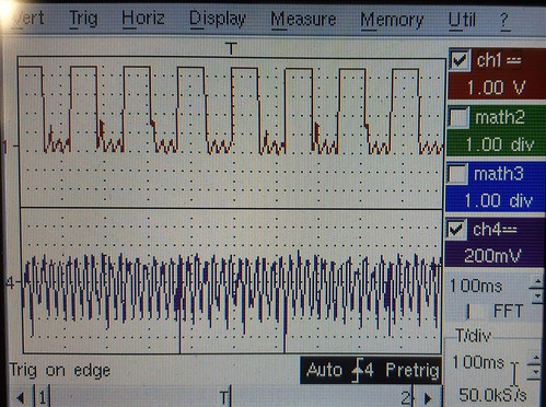 20190325_073558 by Alexandru Bogdan Munteanu, en Flickr[/img] 20190325_073558 by Alexandru Bogdan Munteanu, en Flickr[/img]Just don't know where I'm wrong, congiguring, measuring? |
|
|
|
| mg512 |
Posted on 03/25/2019 3:56 AM
|
|
1/4 Pounder Posts: 189 Joined: March 04, 2018 |
Are you measuring that directly on the IO3 pin? |
|
|
|

| Jump to Forum: |
Powered by PHP-Fusion Copyright © 2024 PHP-Fusion Inc
Released as free software without warranties under GNU Affero GPL v3
Designed with ♥ by NetriXHosted by skpacman