
Login

Shoutbox
You must login to post a message.
renatoa
07/26/2024 3:49 PM
Bill grubbe and Jk, 
allenb
07/26/2024 5:15 AM
Spiderkw Welcome to HRO!

renatoa
07/24/2024 8:31 AM
ramiroflores and John123,

 ?
?
?renatoa
07/21/2024 1:18 AM
 , Luislobo
renatoa
07/19/2024 11:28 AM
Koepea,
Forum Threads
Newest Threads
Skywalker roaster modsBackground Roast Iss...
Hello from Arkansas
TC4ESP
Green coffee reviews
Hottest Threads
| Skywalker roaster... | [375] |
| TC4ESP | [115] |
| War on Farmers by... | [47] |
| Adventures in flu... | [26] |
| Hello! (soon) Roa... | [17] |
In Memory Of Ginny

Donations
Latest Donations
dmccallum - 10.00
JackH - 25.00
snwcmpr - 10.00
Anonymous - 2.00
Anonymous - 5.00
dmccallum - 10.00
JackH - 25.00
snwcmpr - 10.00
Anonymous - 2.00
Anonymous - 5.00
Users Online
Guests Online: 4
Members Online: 0
Total Members: 8,394
Newest Member: Bill grubbe
Members Online: 0
Total Members: 8,394
Newest Member: Bill grubbe
View Thread
Who is here? 1 guest(s)
Page 1 of 2: 12
|
 TC4 Wiring Help
|
|
| mg512 |
Posted on 05/22/2019 9:34 AM
|
 1/4 Pounder  Posts: 189 Joined: March 04, 2018 |
On my popcorn machine, all metal parts had an earth wire screwed onto them. Ring terminal crimped on the wire, M3 nut and bolt to attach it to the part. I've simply left this untouched, maybe others can chime in on how to best go about it if you're starting from scratch. In any case, make sure you tie it to earth ground (the green and yellow cable coming from the mains power), NOT circuit ground (like GND an Arduino). There also seems to be a difference between countries on what appears to be standard practice. On my Gaggia espresso machine, all the metal casing is earthed, but on a US 110V version of the same machine, there was no earthing at all, just a 2-pin plug. I don't know if that's because of the different voltage, or different legislation, or if there's differences in how mains is wired in these countries. Might be worth asking a local electrician for advice, if in doubt. |
|
|
|
| CharcoalRoaster |
Posted on 05/24/2019 3:29 PM
|
 1 1/2 Pounder  Posts: 640 Joined: April 13, 2012 |
I'm trying to ensure I have the sequence on the wiring for the fan and heat correct for my control panel. In order to provide power coming from the AC Line In to the various components can I utilize a buss bar (one for line and one for neutral)? Meaning, if I run my line in to power a buss then split off lines for ZCD, SSR, fan, and heating element will this work or is there a specific way/order to ensure proper functioning of the TC4? Otherwise I'm having a hard time figuring out how to split off AC for the ZCD from the line in, connect the blower lines and split off to the AC side of my SSRs. |
|
|
|
| mg512 |
Posted on 05/25/2019 12:09 AM
|
|
1/4 Pounder Posts: 189 Joined: March 04, 2018 |
That should work. Anything that allows you to connect all the AC components in parallel should do. I simply crimped two wires onto a tab connector. To be clear, you shouldn't need separate lines for the SSR and heater - the SSR goes in series with the heater, like a switch. Same for the random-fire SSR and the AC fan. So in your setup you would have three lines: ZCD, heater (+SSR), fan (+SSR). |
|
|
|
| CharcoalRoaster |
Posted on 05/25/2019 6:53 AM
|
|
1 1/2 Pounder Posts: 640 Joined: April 13, 2012 |
I have two separate AC lines in -- (1) 240v 30a = heater (2) 120v 20a = fan Currently I have the 120v line into the buss with fan, SSR, and ZCD all wired to the bus (line + neutral on separate terminals of course), but if I understand you correctly I'll need a third AC line dedicated for the ZCD? In order that... (1) Line-in > Heater > SSR > TC4 (series) (2) Line-in > Fan > SSR > TC4 (series) (3) Line-in > ZCD > TC4 (series) If I've got that right then would you mind clarifying what you mean by "Anything that allows you to connect all the AC components in parallel should do."? Thanks again! |
|
|
|
| CK |
Posted on 05/25/2019 4:07 PM
|
|
1/2 Pounder  Posts: 252 Joined: December 07, 2018 |
Here is an image of how the transparent roaster is wired with a TC4, ZCD, and SSRs. I run the roaster off 3 outlets (one outlet each; fan, heat1, heat2) and everything is working fine.
CK attached the following image:

|
|
|
|
| mg512 |
Posted on 05/26/2019 2:07 AM
|
|
1/4 Pounder Posts: 189 Joined: March 04, 2018 |
Quote CharcoalRoaster wrote: I have two separate AC lines in -- (1) 240v 30a = heater (2) 120v 20a = fan Currently I have the 120v line into the buss with fan, SSR, and ZCD all wired to the bus (line + neutral on separate terminals of course), but if I understand you correctly I'll need a third AC line dedicated for the ZCD? In order that... (1) Line-in > Heater > SSR > TC4 (series) (2) Line-in > Fan > SSR > TC4 (series) (3) Line-in > ZCD > TC4 (series) If I've got that right then would you mind clarifying what you mean by "Anything that allows you to connect all the AC components in parallel should do."? Thanks again! Oh, no, I wasn't thinking of the incoming lines, I meant the number of lines splitting off the bus. I also hadn't realised that you had both 120V and 240V. You don't need any extra incoming lines. I was just trying to say that you should connect the SSR and fan in series, not both in parallel directly to the busses. So you would have one 120V line coming in, and you split both the live and neutral in two with a bus each. One live-neutral pair goes into the ZCD. The other live goes to one of the AC terminals on the SSR, then from the second AC terminal of the SSR a wire goes to one terminal of the fan motor, and the second fan motor terminal connects to the remaining neutral wire. And same with the 240V line - live goes to SSR, from there a wire to the heater, and from there back to neutral. The TC4 connects to the DC / control side of the SSRs, not really "in series" with anything. In fact, not connected electrically to any of the AC lines at all. Does that all make sense? |
|
|
|
| CharcoalRoaster |
Posted on 05/27/2019 7:00 AM
|
|
1 1/2 Pounder Posts: 640 Joined: April 13, 2012 |
I think I've determined at least part of the source of my confusion -- my 240v line is a 4-wire (2 Hot, Neutral, GND) and I'm not seeing where to to run my other hot line? My heating element needs two hot 120v lines wired to it. Does this mean I need an additional SSR? If so... (1) Do I run a neutral line from the neutral bus inside the breaker panel to each SSR then? (2) Where do I connect the second SSR to the TC4? |
|
|
|
| renatoa |
Posted on 05/27/2019 7:28 AM
|
|
Administrator Posts: 3104 Joined: September 30, 2016 |
If your house is according to this schematic... http://hyperphysi...sehld.html ... then a single SSR on either 240V hot line is enough. Edited by JackH on 05/27/2019 8:21 AM |
|
|
|
| CharcoalRoaster |
Posted on 05/27/2019 7:53 AM
|
|
1 1/2 Pounder Posts: 640 Joined: April 13, 2012 |
If I only have one SSR then wouldn't one leg always remain hot? Since the SSR acts like a switch and if only one hot leg is controlled by it then as soon as main power is turned on won't my heating element begin to receive "uncontrolled" power and heat up? |
|
|
|
| renatoa |
Posted on 05/27/2019 11:37 AM
|
|
Administrator Posts: 3104 Joined: September 30, 2016 |
Nope, because your heater is connected to the other hot line, having no connection to the neutral line. You have a current flow if a load is connected: - between any hot line and the neutral line (120V lines case) - between the two hot lines (240V case) In both cases placing a SSR on the hot line will do the job. |
|
|
|
| CharcoalRoaster |
Posted on 05/27/2019 12:55 PM
|
|
1 1/2 Pounder Posts: 640 Joined: April 13, 2012 |
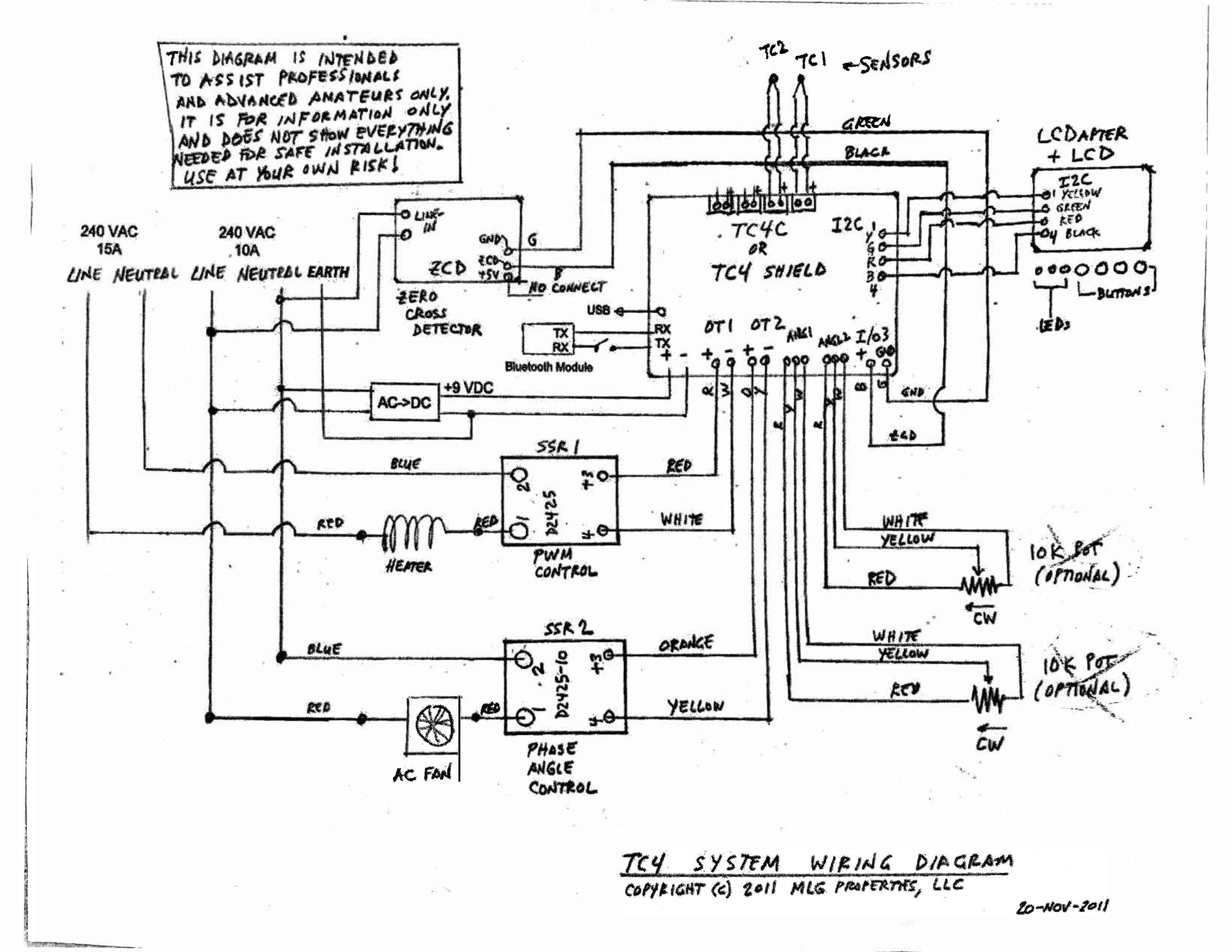
Quote mg512 wrote: Quote CharcoalRoaster wrote: I have two separate AC lines in -- (1) 240v 30a = heater (2) 120v 20a = fan Currently I have the 120v line into the buss with fan, SSR, and ZCD all wired to the bus (line + neutral on separate terminals of course), but if I understand you correctly I'll need a third AC line dedicated for the ZCD? In order that... (1) Line-in > Heater > SSR > TC4 (series) (2) Line-in > Fan > SSR > TC4 (series) (3) Line-in > ZCD > TC4 (series) If I've got that right then would you mind clarifying what you mean by "Anything that allows you to connect all the AC components in parallel should do."? Thanks again! Oh, no, I wasn't thinking of the incoming lines, I meant the number of lines splitting off the bus. I also hadn't realised that you had both 120V and 240V. You don't need any extra incoming lines. I was just trying to say that you should connect the SSR and fan in series, not both in parallel directly to the busses. So you would have one 120V line coming in, and you split both the live and neutral in two with a bus each. One live-neutral pair goes into the ZCD. The other live goes to one of the AC terminals on the SSR, then from the second AC terminal of the SSR a wire goes to one terminal of the fan motor, and the second fan motor terminal connects to the remaining neutral wire. And same with the 240V line - live goes to SSR, from there a wire to the heater, and from there back to neutral. The TC4 connects to the DC / control side of the SSRs, not really "in series" with anything. In fact, not connected electrically to any of the AC lines at all. Does that all make sense? What you said makes sense but I can't reconcile it with the diagram furnished to me from Chad -- so maybe you can help me interpret this appropriately... In the wiring diagram it shows the incoming neutral connected to the second AC terminal of the SSR. What you're describing is splitting the hot line between the two SSR terminals and just connecting the fan neutral to the neutral buss. Am I understanding this correctly?
CharcoalRoaster attached the following image:
|
|
|
|
| renatoa |
Posted on 05/27/2019 2:22 PM
|
|
Administrator Posts: 3104 Joined: September 30, 2016 |
That schematic could make sense in Europe, where 240V has a neutral and a hot line. In US 240V has both line hot, neutral is for 120V only. So ignore the "neutral" labeling for 240V inputs in the left side of schematic, they are both hot. |
|
|
|
| CharcoalRoaster |
Posted on 05/27/2019 3:19 PM
|
|
1 1/2 Pounder Posts: 640 Joined: April 13, 2012 |
Ahhhhh yes, of course -- I didn't even think about the fact that this is wiring from down under (similar to Europe, right?). Got it all wired up. Last thing is the LCD and I'll plug it in to see how things go. Thanks everyone! |
|
|
|

Page 1 of 2: 12
| Jump to Forum: |
Powered by PHP-Fusion Copyright © 2024 PHP-Fusion Inc
Released as free software without warranties under GNU Affero GPL v3
Designed with ♥ by NetriXHosted by skpacman