
Login

Shoutbox
You must login to post a message.
renatoa
07/26/2024 3:49 PM
Bill grubbe and Jk, 
allenb
07/26/2024 5:15 AM
Spiderkw Welcome to HRO!

renatoa
07/24/2024 8:31 AM
ramiroflores and John123,

 ?
?
?renatoa
07/21/2024 1:18 AM
 , Luislobo
renatoa
07/19/2024 11:28 AM
Koepea,
Forum Threads
Newest Threads
Skywalker roaster modsBackground Roast Iss...
Hello from Arkansas
TC4ESP
Green coffee reviews
Hottest Threads
| Skywalker roaster... | [376] |
| TC4ESP | [115] |
| War on Farmers by... | [47] |
| Adventures in flu... | [26] |
| Hello! (soon) Roa... | [17] |
In Memory Of Ginny

Donations
Latest Donations
dmccallum - 10.00
JackH - 25.00
snwcmpr - 10.00
Anonymous - 2.00
Anonymous - 5.00
dmccallum - 10.00
JackH - 25.00
snwcmpr - 10.00
Anonymous - 2.00
Anonymous - 5.00
Users Online
Guests Online: 3
Members Online: 0
Total Members: 8,394
Newest Member: Bill grubbe
Members Online: 0
Total Members: 8,394
Newest Member: Bill grubbe
View Thread
Who is here? 1 guest(s)
 SR800/SR540 Fan Current TC4+
|
|
| dwertz |
Posted on 10/23/2022 2:58 AM
|
|
Newbie  Posts: 45 Joined: October 19, 2022 |
Why 5V? The optocoupler anode is connected to 12V on the power board. Unless I am totally missing how you are proposing making the connection. The way I see it you have gnd and the optocoupler cathode available on the cable between the CPU board and the power board. You would connect gnd, and OT1 / OT2 P1 to the cathode via the 1k resistor. The 5V on the TC4 would not be involved. Unless you are trying to avoid connecting the gnds together? But in that case, you would need to gain access to the optocoupler anode and disconnect it from the 12V on the power board. Edited by dwertz on 10/23/2022 3:05 AM |
|
|
|
| renatoa |
Posted on 10/23/2022 3:02 AM
|
|
Administrator Posts: 3104 Joined: September 30, 2016 |
Quote dwertz wrote: I don't know anything about the TC4/TC4+ firmware, but anything I use will have logic to prevent heater energization without the fan set to some minimum speed. Ideally you would have access to a temperature sensor that is tightly thermally coupled to the heater. That way you could detect heater overtemperature conditions in case of a fan failure or airflow restriction due to clogged chaff collector and shut down the heater. Perhaps one of these days I will open the unit back up and check out the built-in temperature sensor. The TC4 software logic handles only cases where the operator reduce the fan speed under a preset value, and in this case the heater power is cut at all. There is no code to monitor unexpected rapid rise of heat without any explanation, maybe because in this case the detection of FC event could be compromised, I guess. Such protections can be added very easy in code, for example in my TC4ESP fork I introduced a high temperature value alarm for ET, preset at 260C. Also an alarm based on rise more than ... twice... faster than the average rise of last minute, could be effective and do not disturb FC detection. The later was just an idea coming in my mind while typing the above. Anyway, what I mean is that personally I don't feel the need for another separate temperature sensor and monitoring circuits. Coffee roasting is not an unattended activity, and you should have mains circuit breaker handy for all scenarios. |
|
|
|
| renatoa |
Posted on 10/23/2022 3:07 AM
|
|
Administrator Posts: 3104 Joined: September 30, 2016 |
If still interest for such protection with separate sensor circuitry, @CK did such job, check here: https://homeroast...post_71738 |
|
|
|
| renatoa |
Posted on 10/23/2022 3:15 AM
|
|
Administrator Posts: 3104 Joined: September 30, 2016 |
Quote dwertz wrote: Why 5V? The optocoupler anode is connected to 12V on the power board. Unless I am totally missing how you are proposing making the connection. The way I see it you have gnd and the optocoupler cathode available on the cable between the CPU board and the power board. You would connect gnd, and OT1 / OT2 P1 to the cathode via the 1k resistor. The 5V on the TC4 would not be involved. Unless you are trying to avoid connecting the gnds together? But in that case, you would need to gain access to the optocoupler anode and disconnect it from the 12V on the power board. You are right, if keeping the 12V source the resistor value of 1kO is good. As I wrote, my image was to handle the optocoupler as a SSR and connect both pins to TC4. Ignored the 12V supply at all when thinking about this, supposing even it can be removed at all with this mod. Btw, what other circuits remains to be powered inside if TC4 rules them all ? Edited by renatoa on 10/23/2022 3:16 AM |
|
|
|
| dwertz |
Posted on 10/23/2022 3:16 AM
|
|
Newbie Posts: 45 Joined: October 19, 2022 |
Quote renatoa wrote: Anyway, what I mean is that personally I don't feel the need for another separate temperature sensor and monitoring circuits. Coffee roasting is not an unattended activity, and you should have mains circuit breaker handy for all scenarios. Fair enough! And after looking at the pictures in the thread you linked, it appears that there is a thermal fuse and a bimetallic thermostat on the heater, so unless there is no airflow at all, one of those items should protect against catastrophic damage. Edited by dwertz on 10/23/2022 3:40 AM |
|
|
|
| dwertz |
Posted on 10/23/2022 3:38 AM
|
|
Newbie Posts: 45 Joined: October 19, 2022 |
Quote renatoa wrote: Btw, what other circuits remains to be powered inside if TC4 rules them all ? Nothing else is required. There is a temperature sensor of some sort that measures air temperature entering the roast chamber or possibly the temperature of the metal the roast chamber sits on. I am not totally sure what it is measuring. But I don't feel is necessary if there is a probe in the roast chamber. The power board and the CPU board are powered up if the unit is plugged in. The beauty of tapping into the optocoupler control signals is that TC4 can fire the TRIACs or the built in CPU can fire the TRIACs. So, you can use the roaster with either front panel control or computer control. No functionality is lost. |
|
|
|
| Gullygossner |
Posted on 10/23/2022 7:35 AM
|
|
1/4 Pounder  Posts: 95 Joined: January 06, 2019 |
Quote renatoa wrote: Quote This looks directly compatible with OT1/2 outputs of TC4 shield, so again no need to change any bit, except the resistor, but lower value because we have 5V instead 12V. Typical Arduino schematics are using 220-330 Ohms for this task, to ensure a minimum of 10 mA for the optocoupler to fire. With 1kO the current will be about 3 mA, not enough. Except this, just handle the optocoupler inputs as a SSR in the TC4 schematic. So if I am reading corrrectly...... On the hardware side OT1 goes to the yellow heater command wire with a 220-330ohm resistor in series OT2 goes to the brown fan command wire with a 220-330ohm resistor in series Is a connection the orange zero cross wire to IO2 required? with a resistor? Then on the artisanq firmware CONFIG_PAC2 // phase angle control on OT1 (heater) and OT2 (fan); IO2 used to read the ZCD |
|
|
|
| renatoa |
Posted on 10/23/2022 8:39 AM
|
|
Administrator Posts: 3104 Joined: September 30, 2016 |
Orange to IO2 is mandatory, not required... without ZC there is no phase angle control. 220-330ohm only if you are using tc TC4 5v power for the optocoupler anode, that actually is connected to 12V in the schematic from post #23. If you are using only the yellow/brown wires and keep the 12v source, as in that schematic, then use 1kO. The comment about CONFIG_PAC2 above is a bit outdated, the right and current definition is below: https://github.co...user.h#L24 This not affect your fan control plans, the difference is about the heater control. Edited by renatoa on 10/24/2022 1:01 AM |
|
|
|
| dwertz |
Posted on 10/23/2022 7:04 PM
|
|
Newbie Posts: 45 Joined: October 19, 2022 |
Houston, we have a problem. On the schematic, I show a ground symbol. I drew it as such because the board labels it as Gnd, but it is in fact not ground. It is line neutral. As such, we can not connect to it. It is not touch safe. The only grounded component is the metal tray the roasting chamber sits on. We could disconnect the TRIAC driver from the 12V and use the 5V from the TC4, but we still have the issue that the ZC signal is referenced to the line neutral. Disconnecting the TRIAC driver from the 12V also means the cpu board would no longer control fan or heat. I think I will add an extra layer of optoisolators. Two for the control and one for the zero crossing detector. |
|
|
|
| Gullygossner |
Posted on 10/23/2022 8:54 PM
|
|
1/4 Pounder Posts: 95 Joined: January 06, 2019 |
Quote dwertz wrote: Houston, we have a problem. On the schematic, I show a ground symbol. I drew it as such because the board labels it as Gnd, but it is in fact not ground. It is line neutral. As such, we can not connect to it. It is not touch safe. The only grounded component is the metal tray the roasting chamber sits on. We could disconnect the TRIAC driver from the 12V and use the 5V from the TC4, but we still have the issue that the ZC signal is referenced to the line neutral. Disconnecting the TRIAC driver from the 12V also means the cpu board would no longer control fan or heat. I think I will add an extra layer of optoisolators. Two for the control and one for the zero crossing detector. Wouldn't the gnd cable on the five pin connector suffice as ground or is this the ground you are referencing that is to neutral? Also, Tom was kind enough to post some additional circuit drawings. http://cholla.mmt...k/circuit/ Edited by renatoa on 10/24/2022 1:03 AM |
|
|
|
| dwertz |
Posted on 10/23/2022 10:50 PM
|
|
Newbie Posts: 45 Joined: October 19, 2022 |
That is correct, the gnd on the five-pin cable is actually connected to neutral of the 120V AC via a bridge rectifier. Normally neutral is within a few volts of actual ground, but you can't rely on that. And the bridge complicates it even more. There will actually be a 12Vp-p waveform there that varies between 0.7V and -12.7V. And if the house wiring is messed up .... Well let's just say it can be a lot worse. In the stock SR800, you can't touch any of the circuitry. Everything is hidden behind plastic. In our situation we want to connect to other electronics, including electronics that may actually be grounded. I will check out the new information Tom Posted Edited by dwertz on 10/24/2022 5:49 PM |
|
|
|
| dwertz |
Posted on 10/24/2022 12:26 AM
|
|
Newbie Posts: 45 Joined: October 19, 2022 |
OK I took a peek at Tom's new circuit page. There is an error in the opamp circuit for U3_B. The drawing is missing a diode between U3_A output and the parallel RC to gnd. U3_B is a peak detected version of U3_A minus one diode drop. I think it must be connected to one of the analog inputs of the PIC. It can be used to measure the line voltage. Perhaps shut things down if there is a brown out or poor wiring to the SR800. Getting the Orange wire into a format we can use will take a little more work. but it is doable. It is essentially a scaled half wave rectified version of the input voltage. We need to drive an optocoupler with it. Probably squaring it up first. Like Tom measured on the internal version, the duty cycle won't be 50%, but we can use different delays for the positive and negative transitions. |
|
|
|
| renatoa |
Posted on 10/24/2022 8:27 AM
|
|
Administrator Posts: 3104 Joined: September 30, 2016 |
Quote dwertz wrote: Houston, we have a problem. On the schematic, I show a ground symbol. I drew it as such because the board labels it as Gnd, but it is in fact not ground. It is line neutral. As such, we can not connect to it. It is not touch safe. The only grounded component is the metal tray the roasting chamber sits on. We could disconnect the TRIAC driver from the 12V and use the 5V from the TC4, but we still have the issue that the ZC signal is referenced to the line neutral. Disconnecting the TRIAC driver from the 12V also means the cpu board would no longer control fan or heat. I think I will add an extra layer of optoisolators. Two for the control and one for the zero crossing detector. Indeed... little problem... a look at the dimmer schematic will tell the right wiring of everything. This is the most minimal and functional way to do these things working. Then try to equate existing SR parts with the dimmer schematic, adding the missing puzzle parts. For example the SR existing bridge can be equated to the dimmer ZC circuit bridge, just route the bridge outputs to the optocoupler diode inputs, in series with a current limiting resistor of 1 kO, and use the optoisolator transistor output to drive INT pin IO2. No more using the orange wire at all... gone ... Also, you should be aware that these should be two different types of opto...something. The ZC side should be with transistor output, while the control side they are opto triacs. Just a headsup... to not be tempted to use for ZC the same optocoupler as for control. Edited by renatoa on 10/24/2022 8:36 AM |
|
|
|
| dwertz |
Posted on 10/24/2022 1:43 PM
|
|
Newbie Posts: 45 Joined: October 19, 2022 |
I measured the SR800 "GND" this morning and it is exactly as expected. So yes, we need more optocouplers than originally assumed.
dwertz attached the following image:

Edited by dwertz on 10/24/2022 7:22 PM |
|
|
|
| renatoa |
Posted on 10/25/2022 1:39 AM
|
|
Administrator Posts: 3104 Joined: September 30, 2016 |
Just one more  Or, simpler to do, imo... as wiring I mean... get a robotdyn dimmer and use it for ZC and fan. Keep only the heater circuit with original SR components, fed from OT1. |
|
|
|
| dwertz |
Posted on 10/25/2022 2:06 AM
|
|
Newbie Posts: 45 Joined: October 19, 2022 |
I think I agree, just slapping in a ZC circuit is probably simplest. |
|
|
|
| Gullygossner |
Posted on 10/25/2022 6:48 AM
|
|
1/4 Pounder Posts: 95 Joined: January 06, 2019 |
Quote renatoa wrote: Just one more Or, simpler to do, imo... as wiring I mean... get a robotdyn dimmer and use it for ZC and fan. Keep only the heater circuit with original SR components, fed from OT1. What would the connections look like to achieve that? I've got a robotdyn dimmer already so it's just a matter of figuring out the wiring. |
|
|
|
| renatoa |
Posted on 10/25/2022 8:23 AM
|
|
Administrator Posts: 3104 Joined: September 30, 2016 |
Back to #11 post schematic. First, the SR800 side: - J1 is the A/C IN connector/screws block, there you should connect the mains wires, taken from ... any point that is most comfortable for you. - J2 is the OUT/LOAD block, the fan should be connected there together with that 100 ohm resistor, that reduce voltage to 30V. What exactly which wires means the above is hard to say without a SR800 dissected on my table... Then, TC4 side: - Zero C pin goes to INT pin/ IO2 of TC4 - Gnd, the TC4 ground pin - PWM pin (dimmer) goes to HTR control pin of TC4 (D9) Not the OT1 headers ! |
|
|
|
| dwertz |
Posted on 11/27/2022 11:56 PM
|
|
Newbie Posts: 45 Joined: October 19, 2022 |
OK I did it. Still need to get arduino connected, but the controls work from the connector.
dwertz attached the following image:

|
|
|
|
| dwertz |
Posted on 11/28/2022 12:00 AM
|
|
Newbie Posts: 45 Joined: October 19, 2022 |
The biggest spend was a fancy connector
dwertz attached the following image:

|
|
|
|
| dwertz |
Posted on 11/28/2022 12:10 AM
|
|
Newbie Posts: 45 Joined: October 19, 2022 |
Quick little Demo https://youtube.c...-QIzJxuiDE
Edited by dwertz on 11/28/2022 12:31 AM |
|
|
|
| Gullygossner |
Posted on 12/03/2022 7:27 AM
|
|
1/4 Pounder Posts: 95 Joined: January 06, 2019 |
Quote dwertz wrote: OK I did it. Still need to get arduino connected, but the controls work from the connector. This is fantastic! Would you mind doing a little write up of how you got it working? |
|
|
|
| dwertz |
Posted on 12/04/2022 10:46 PM
|
|
Newbie Posts: 45 Joined: October 19, 2022 |
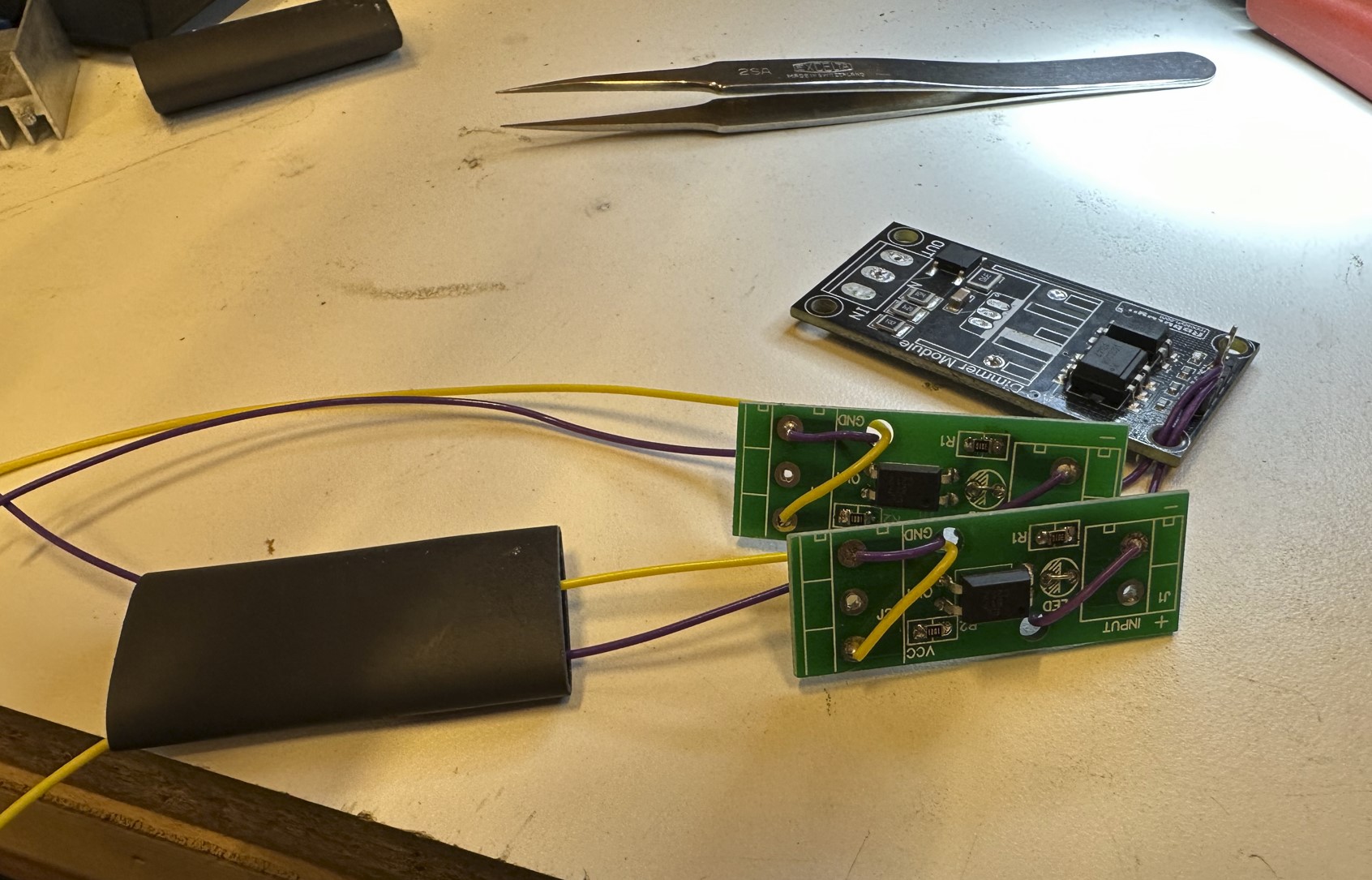
Basically, I just did what renatoa suggested. I did do a slight modification though. I chose not to use the Triac on the robotdyn dimmer. I just used it for the zero-crossing circuit. Then I used two separate optocouplers. One for the Heater and one for the fan. The transistor output and resistor of the optocoupler is wired in parallel with the transistor and resistor on the original CPU board. That way the original CPU board continues to have control, and the optocouplers have control. Either can fire the original Triacs. One of the goals was to not break the roasters original functionality. I did change the resistors on the optocoupler boards. I used 300 ohms on the arduino side for compatibility with 3.3V or 5V logic, and 1k on the transistor side to match the resistors on the original CPU board. Tapping into the AC mains for the zero-crossing circuit feels a bit sketchy. Just soldering wires down like I did is not very robust. We will see how long it lasts. I am not representing this as an engineered or safe solution. This is just what I did for fun. Definitely proceed at your own risk. Now that it is modified, I am not sure why I did it LOL. Is it so I can use the sliders in Artisan rather than the knob on the roaster? That is clearly not worth it. Originally the goal was to use PID control and have the computer control the heater to follow a predetermined roast profile. But I am finding the temperature display in Artisan to be really lagging behind control inputs, so I am not convinced how well PID control is going to work. Edited by dwertz on 12/04/2022 11:30 PM |
|
|
|
| dwertz |
Posted on 12/04/2022 10:47 PM
|
|
Newbie Posts: 45 Joined: October 19, 2022 |
Optocoupler boards and robotdyn dimmer
dwertz attached the following image:

Edited by dwertz on 12/04/2022 11:06 PM |
|
|
|
| dwertz |
Posted on 12/04/2022 10:51 PM
|
|
Newbie Posts: 45 Joined: October 19, 2022 |
Connectors and unused components removed
dwertz attached the following image:
|
|
|
|

| Jump to Forum: |
Powered by PHP-Fusion Copyright © 2024 PHP-Fusion Inc
Released as free software without warranties under GNU Affero GPL v3
Designed with ♥ by NetriXHosted by skpacman