
Login

Shoutbox
You must login to post a message.
renatoa
07/26/2024 3:49 PM
Bill grubbe and Jk, 
allenb
07/26/2024 5:15 AM
Spiderkw Welcome to HRO!

renatoa
07/24/2024 8:31 AM
ramiroflores and John123,

 ?
?
?renatoa
07/21/2024 1:18 AM
 , Luislobo
renatoa
07/19/2024 11:28 AM
Koepea,
Forum Threads
Newest Threads
Skywalker roaster modsBackground Roast Iss...
Hello from Arkansas
TC4ESP
Green coffee reviews
Hottest Threads
| Skywalker roaster... | [375] |
| TC4ESP | [115] |
| War on Farmers by... | [47] |
| Adventures in flu... | [26] |
| Hello! (soon) Roa... | [17] |
In Memory Of Ginny

Donations
Latest Donations
dmccallum - 10.00
JackH - 25.00
snwcmpr - 10.00
Anonymous - 2.00
Anonymous - 5.00
dmccallum - 10.00
JackH - 25.00
snwcmpr - 10.00
Anonymous - 2.00
Anonymous - 5.00
Users Online
Guests Online: 5
Members Online: 0
Total Members: 8,394
Newest Member: Bill grubbe
Members Online: 0
Total Members: 8,394
Newest Member: Bill grubbe
View Thread
Who is here? 1 guest(s)
Page 1 of 2: 12
|
 DIY SSR with '555
|
|
| seedlings |
Posted on 01/19/2008 8:32 PM
|
 1 1/2 Pounder  Posts: 4226 Joined: June 27, 2007 |
If you view all and scroll to the bottom, there's my first roaster video! It's a modified soup can and a wire mesh pencil holder attached to a drill. I see I don't have any heatgun and breadmaker shots in there.... but there's my Fender Champ circuit! CHAD Roaster: CoffeeAir II 2# DIY air roaster
Grinder: Vintage Grindmaster 500 Brewers: Vintage Cory DCU DCL, Aeropress, Press, Osaka Titanium pourover |
|
|
|
| bvwelch |
Posted on 01/21/2008 12:37 PM
|
 1 1/2 Pounder Posts: 1064 Joined: December 27, 2007 |
I've found a better approach to using the '555. I'll be testing this out on the bench, and updating the schematic accordingly. The advantage to this new circuit is that you can keep the period of the timer circuit constant, and vary only the duty cycle. With the old circuit, both the duty cycle and the period of the timer changed at the same time, which really made it hard to choose the best values for the resistor, potentiometer, and capacitor. You can read about it here. It is a nice tutorial about the 555 as well. http://www.dprg.o...index.html Bill Edited by bvwelch on 01/21/2008 12:38 PM |
|
|
|
| seedlings |
Posted on 01/21/2008 1:19 PM
|
|
1 1/2 Pounder Posts: 4226 Joined: June 27, 2007 |
On the other circuit I used an audio taper pot and that seemed to give me pretty smooth control versus a linear pot. So with this circuit, we could have the period set for, say, 1 second, with the element coming on for various fractions of a second if R1=250K, C1= 5.76uF... Can I do math? CHAD Roaster: CoffeeAir II 2# DIY air roaster
Grinder: Vintage Grindmaster 500 Brewers: Vintage Cory DCU DCL, Aeropress, Press, Osaka Titanium pourover |
|
|
|
| bvwelch |
Posted on 01/21/2008 2:45 PM
|
|
1 1/2 Pounder Posts: 1064 Joined: December 27, 2007 |
Well, I think you have the idea, but one issue might be that resistors and capacitors only come in standard sizes, so you might have to adjust your R value once you've chosen your C value. The MOC3041 is a zero-crossing driver, which means that the smallest incremental change in the on/off timing is one-half of the sine wave, or about 8 milliseconds. So, your idea of a one second period will give you a lot of range. You could probably be OK with half that amount. This is the sort of thing that I want to experiment with. I also plan to try out the "random phase" drivers, which will be more like your router speed controller. But I've got a lot more reading to do about that first. Your comment about the audio taper pot has me puzzled. I'll have to think about that some... Bill |
|
|
|
| seedlings |
Posted on 01/21/2008 3:45 PM
|
|
1 1/2 Pounder Posts: 4226 Joined: June 27, 2007 |
The audio taper just changes the resistance on a logorithmic curve instead of linear. Both start and end at the same place, just take different paths to get there. CHAD
seedlings attached the following image:
![pots[671].gif](../forum/attachments/pots[671].gif)
Edited by seedlings on 01/21/2008 3:46 PM Roaster: CoffeeAir II 2# DIY air roaster
Grinder: Vintage Grindmaster 500 Brewers: Vintage Cory DCU DCL, Aeropress, Press, Osaka Titanium pourover |
|
|
|
| bvwelch |
Posted on 01/21/2008 8:11 PM
|
|
1 1/2 Pounder Posts: 1064 Joined: December 27, 2007 |
The puzzling part is why it would be better in your circuit. I think it probably means that the linear pot was covering a much wider range than was useful to you. Bill |
|
|
|
| bvwelch |
Posted on 01/26/2008 1:10 PM
|
|
1 1/2 Pounder Posts: 1064 Joined: December 27, 2007 |
Quote bvwelch wrote: I've found a better approach to using the '555. I'll be testing this out on the bench, and updating the schematic accordingly. The advantage to this new circuit is that you can keep the period of the timer circuit constant, and vary only the duty cycle. With the old circuit, both the duty cycle and the period of the timer changed at the same time, which really made it hard to choose the best values for the resistor, potentiometer, and capacitor. You can read about it here. It is a nice tutorial about the 555 as well. http://www.dprg.o...index.html Bill I may start a different thread on this subject, but the new approach works well. I'm using it, like Doug Strait's mods, to control the Wearever Pumper with DC. The new '555 circuit really works well. Photos at my web site, look for "boost..." they are over-size for this web site. http://bvwelch.co... Bill |
|
|
|
| seedlings |
Posted on 01/26/2008 8:55 PM
|
|
1 1/2 Pounder Posts: 4226 Joined: June 27, 2007 |
Here, Bill, I resized your pics! Looks good. Could you describe in your own words how this circuit helps? Thanks! CHAD 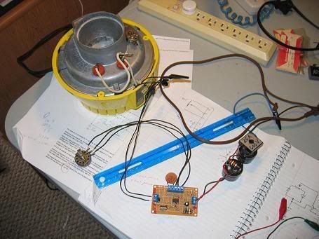 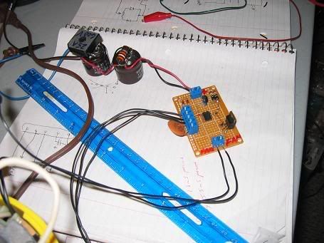 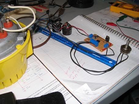
Roaster: CoffeeAir II 2# DIY air roaster
Grinder: Vintage Grindmaster 500 Brewers: Vintage Cory DCU DCL, Aeropress, Press, Osaka Titanium pourover |
|
|
|
| bvwelch |
Posted on 01/26/2008 11:05 PM
|
|
1 1/2 Pounder Posts: 1064 Joined: December 27, 2007 |
Thanks Chad! There a three things going on with this photo: 1) Doug's idea was to put the mods inside the pumper -- it is big and roomy in there. So what you see laying on my bench, I plan to install inside the popper. 2) the '555 uses that approach we discussed above, where the frequency or period of the pulse-width-modulation is constant, and only the duty cycle varies when you twist the knob. With the initial circuit, both the frequency and the duty cycle varied continuously, which made it complicated to find good values of R and C. 3) The pumper, like the Poppery 1, is wired from the factory as a 120 volt AC motor -- not like most modern poppers, which have a 20 volt DC motor. Anyway, the motors in the pumper and the Poppery 1 are actually "universal" motors, which means they can run on DC just as well as AC. And by rectifying the AC into DC, and adding the large "filter" capacitor, you can get about 160 volts DC for the motor, which means you can "boost" its speed, without a transformer. Since it is a DC circuit, the power mosfet is used, instead of a triac. I'll upload a schematic for this soon. I do plan to try a variation of this idea, on the 20 volt DC poppers. But I'll have to be careful not to accidentally hit them with too much voltage and zap them. Next I plan to try the new style '555 circuit on my heater triac circuit. It should result in a design that is easier to replicate with whatever R and C values you have on hand. Bill |
|
|
|
| seedlings |
Posted on 01/26/2008 11:32 PM
|
|
1 1/2 Pounder Posts: 4226 Joined: June 27, 2007 |
EXCELLENT!s:2s:2s:2 CHAD Roaster: CoffeeAir II 2# DIY air roaster
Grinder: Vintage Grindmaster 500 Brewers: Vintage Cory DCU DCL, Aeropress, Press, Osaka Titanium pourover |
|
|
|
| seedlings |
Posted on 02/01/2008 12:42 PM
|
|
1 1/2 Pounder Posts: 4226 Joined: June 27, 2007 |
Hey Bill, could one pot and one 555 control multiple triacs? Like if I wanted three 20amp heat elements... or one one knob to control the heat element triac AND the blower motor triac... Maybe using a different value for the 220 ohm resistor? CHAD Roaster: CoffeeAir II 2# DIY air roaster
Grinder: Vintage Grindmaster 500 Brewers: Vintage Cory DCU DCL, Aeropress, Press, Osaka Titanium pourover |
|
|
|
| bvwelch |
Posted on 02/01/2008 1:21 PM
|
|
1 1/2 Pounder Posts: 1064 Joined: December 27, 2007 |
Chad, You're making me nervous. :-) I think I would just connect three different resistors to the output of the '555. I don't see why you would want to control the heat and fan with the same knob. By the way, I'd recommend going to the improved '555 circuit if you want to do a motor. And actually, use a different driver chip (one of the others that I sent you). Let me look at my schematic to make sure which one I chose. Then it will be like your router speed controller. You could use the "dimmer-style" driver chip for both the motor/fan and the heat. We'll have to change the thread to DIY router speed controller, since SSRs seem to be the zero-crossing kind. Clear as mud? Ask questions, and I'll write back when I have more time. Edit: I took a quick look-- I haven't tested the non-zero crossing triac drivers yet. Sorry. I'll let you know when I get a chance to try them. -bill Edited by bvwelch on 02/01/2008 5:21 PM |
|
|
|

Page 1 of 2: 12
| Jump to Forum: |
Powered by PHP-Fusion Copyright © 2024 PHP-Fusion Inc
Released as free software without warranties under GNU Affero GPL v3
Designed with ♥ by NetriXHosted by skpacman